Noise Exposure
ABR testing is a common method used to investigate the link between noise exposure and hearing loss. As a result, some of our customers have asked for more information on using their TDT system for implementing noise exposure in the lab. This section includes basic information on noise delivery and our best advice for lab set up. For investigators new to noise exposure experiments, we also recommend consulting other researchers with experience in the field.
Noise exposure testing typically compares the results of hearing measurements before and after exposure. The goal of noise exposure delivery in the lab is to reproduce or simulate the effects, including hearing damage or deafening, of real-world noise exposure.
Key elements of noise exposure:
-
High dB noise delivery
-
Extended duration (hours) of continuous sound delivery
-
Filtered or unfiltered noise
Note
Tones can also be used to investigate frequency-specific hearing loss
Hardware Requirements:
-
TDT Signal Processor, such as the RZ6 Auditory Processor
-
Amplifier
-
Speaker
-
Microphone and microphone amplifier (for calibration and testing enclosure)
-
PC for experiment control
When considering your hardware set-up, the first question to ask is what level sound you will be using. The TDT amplifiers and speakers are not intended for delivering sound greater than 100 dB over long periods, typical of most noise exposure protocols. That type of use will damage the speaker and will almost certainly result in clipping the stimulus. We suggest using an external amplifier and speakers.
External Amplifiers
You might already have an appropriate amplifier in your lab. One of the most common amplifiers we have seen in labs is the Crown D-75 or Crown D-75A. Unfortunately, this is no longer available. If you have one, this is a good choice. If you don't already have a suitable amplifier, we can recommend the CSA 280Z manufactured by JBL (formerly Crown). The CSA 280Z is a two-channel amplifier that provides up to 80 watts of power.
Speakers
Because speaker models change frequently, it is difficult for us to recommend a specific speaker. A commonly available three-way, 6 inch by 9 inch car speaker is a good choice for delivering sound.
Setting Up Signal Generation in RPvdsEx
All of the tasks performed by your RZ6 are configured via Real-time Processor Visual Design Studio, RPvdsEx, files. BioSigRZ and all other TDT software use RPvdsEx files behind the scenes to control TDT hardware. You will use this same software to deliver noise exposure.
The RPvdsEx is a nuts and bolts tool with virtually limitless flexibility, but it wasn't really designed for running experiments. That means the user interface will look a little different from our applications software. For this purpose, however, it will work just fine and all you will need to do when it is time to start signal presentation is open a file and click run.
Before you run signal presentation, however, you will need to make some basic adjustments to the file.
TDT has three versions of a basic timed sound presentation file:
These files are included in the BioSigRZ Examples folder found at:
https://www.tdt.com/files/examples/BioSigRZExamples.zip
After you have downloaded and extracted the folder, choose the file that is right for you and double-click it to run RPvdsEx and open the file.
Modifying the RPvdsEx File
The processing functions that make up this task appear as components ordered and connected in the processing chain and arranged on a large sheet.

You can use the Pan button or the horizontal and vertical scroll bars to move around the sheet. The illustration below shows the circuit and identifies the tasks in each section.
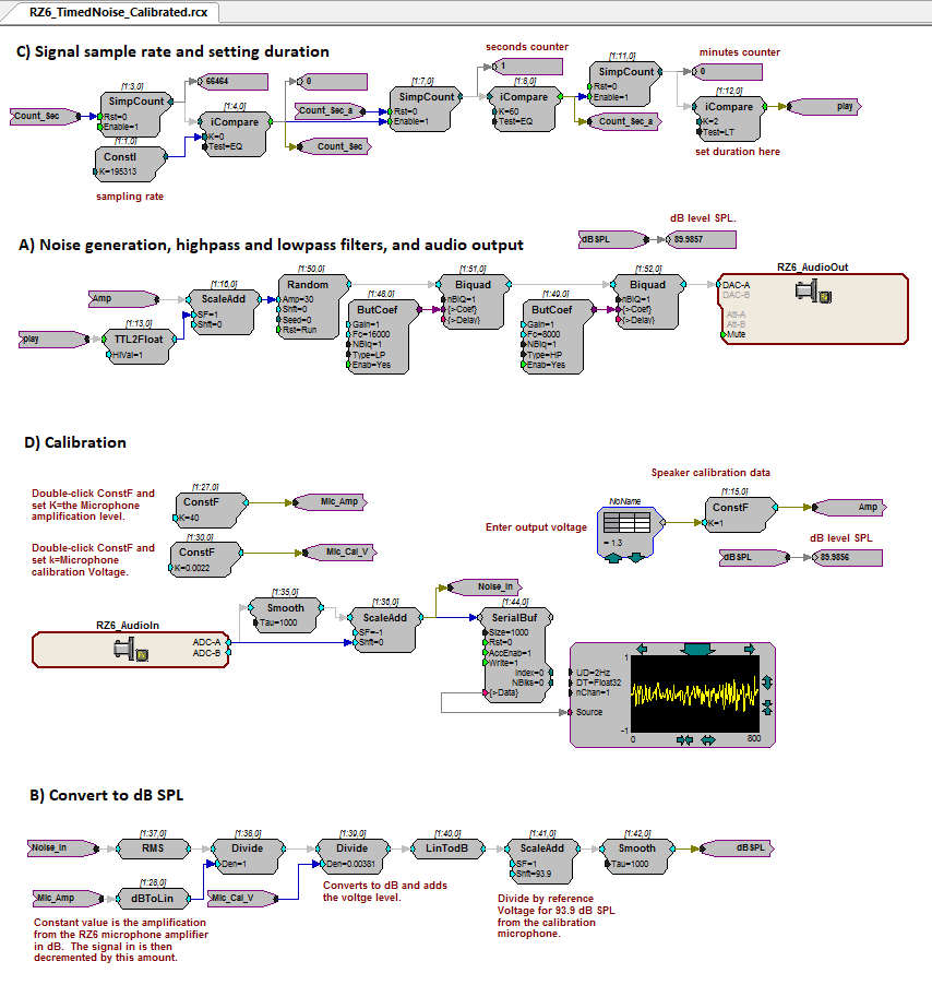 |
| Random Noise Generation Circuit |
Working with Circuit Components
This circuit is configured for you, but you will need to change the properties of some of the components.
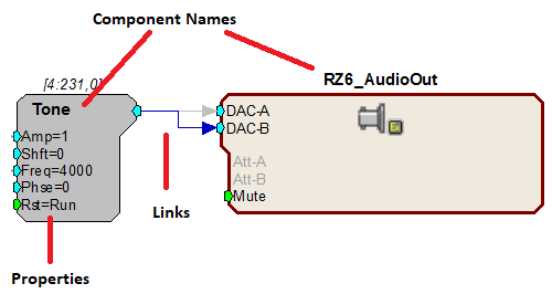 |
| Circuit Segment |
To modify the properties of any component, double-click it and enter a new value in the properties dialog that is displayed and then click OK.
To create a link, double-click an output port on a component, then click the input port on the next component in the circuit.
To add a component, double-click the workspace and select a component.
To delete a component or link, click it and press the DELETE key on your keyboard.
For more information on working with circuits, see the RPvdsEx Manual.
Modify a File
-
Open the appropriate RPvdsEx file.
-
If you are using filtered noise, the first step is setting the filter values. If not, you can skip to the next step.
Find section B, in the illustration above. By default the circuit uses a lowpass filter with a corner frequency at 16 kHz and a highpass filter with a corner frequency at 8 kHz.
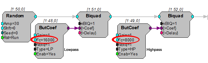
These components generate the filter coefficients used by the Biquad filters. To set the filters, modify the corner frequencies (Fc) in the ButCoef components as needed.
-
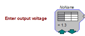
The TDT System outputs a voltage. To ensures the output voltage is calculated correctly for the desired dB results, you need to calibrate the system.
Find section C, in the illustration above. The voltage is set in the circuit segment pictured below. By default, it is set to 1.3 V, which should be a good starting point. For now, leave the default voltage as is.
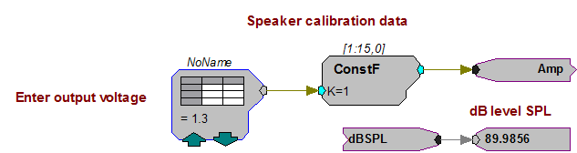
The expected dB SPL is displayed for reference. The actual dB will depend on your complete system, including the external amplifier and speaker.
To begin calibration, place the calibration microphone in the subject enclosure in place of the subject. We recommend the PCB-378C01 PCB microphone and mic amplifier.
-
Enter the microphone sensitivity for your calibration microphone. Find this circuit segment pictured below.
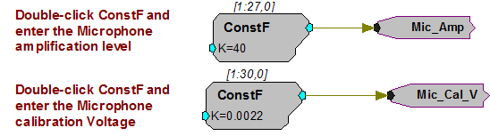
Double-click the first ConstF component and enter the microphone amplification level indicated by the microphone Gain knob setting on the face of the RZ6. Click OK.
Important
The microphone amplification switch on the RZ6 front panel must be set to AMP.
Using the microphone sensitivity provided by the manufacturer, determine the calibration microphone voltage (usually listed on spec sheet in millivolts per Pascal). Double-click the second ConstF component and enter the value in volts. Click OK.
-
Section B of the circuit, calculates the dB SPL. You shouldn't need to make any changes in this segment, but this a good time to save the circuit with a new name.
To run the circuit for calibration:

To begin calibration, make sure the microphone is in place and the chamber is closed, then click the Compile, load, run button on the main toolbar.

To stop presenting the sound, click the Stop button.

To restart, press the Run button.
Note
Both Run and Compile, Load, Run restart the presentation, however, Compile Load, Run also restarts the circuit timer. Run resumes from current value in timer.
-
Use the level recorded by the microphone to adjust the voltage.
To update to the corrected voltage, locate the DataTable component pictured here.
Click the green up or down arrows to adjust the value.
If none of the preset values is suitable, you can double-click the DataTable component to modify the table.
Important
TDT devices are limited to ±10 V. If the calibration results in a voltage outside this range, your stimulus will be clipped and distorted. If this becomes and problem, you need a more sensitive speaker or a more powerful amplifier.
-
Set desired duration, in minutes.
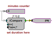
Double-click the iCompare component labeled "set duration here" and enter a value for K equal to the desired number of minutes you want the signal to play. For example, k = 120 for a two hour presentation. Click OK.
-
Save the changes you've made. Be sure the file is saved using a new name.
To run the circuit for presentation:
To begin, click the Compile, load, run button on the main toolbar.
To stop presenting the sound, click the Stop button.
Using Tones
If you are using the timed tone signal file, you will need to set the tone frequency. Find the section of the file pictured below.
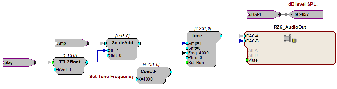
To set the tone frequency:
- Double-click the ConstF component, set the desired frequency in Hz, and click OK. Then run the circuit as explained above.
Preparing a Suitable Enclosure
Noise exposure is performed inside a chamber to protect the researcher's hearing. You will also need an enclosure inside the chamber to limit the movements of the agitated subject and ensure it is positioned near the speaker. If you do not already have a suitable animal enclosure, you can build one from widely available materials. This section provides general recommendations for your chamber and enclosure.
Soundproof the Chamber
Line the inside of the chamber with acoustic foam to eliminate constructive or destructive interference with the signal. See Sound Chamber Fundamentals for more information.
Build the Enclosure
Use mesh hardware cloth to create an oval tube or cylinder with a maximum width that matches your selected speaker. Mesh hardware does not interfere with noise moving through the chamber but will resist the subject's attempts to escape the space and be strong enough to support the weight of a speaker placed at the top of the tube.
Use mesh hardware cloth to create a raised floor a few inches above the acoustic foam and a lowered ceiling a few inches below the speaker. This will prevent the subject from damaging the acoustic foam or the speaker in any attempt to escape the space.
Protect Foam with Replaceable Underpad
Place a blue disposable underpad on the acoustic foam below the tube to collect droppings and prevent damage to the foam.
Position the Speaker
Position the speaker directly above the tube, facing down toward the subject.
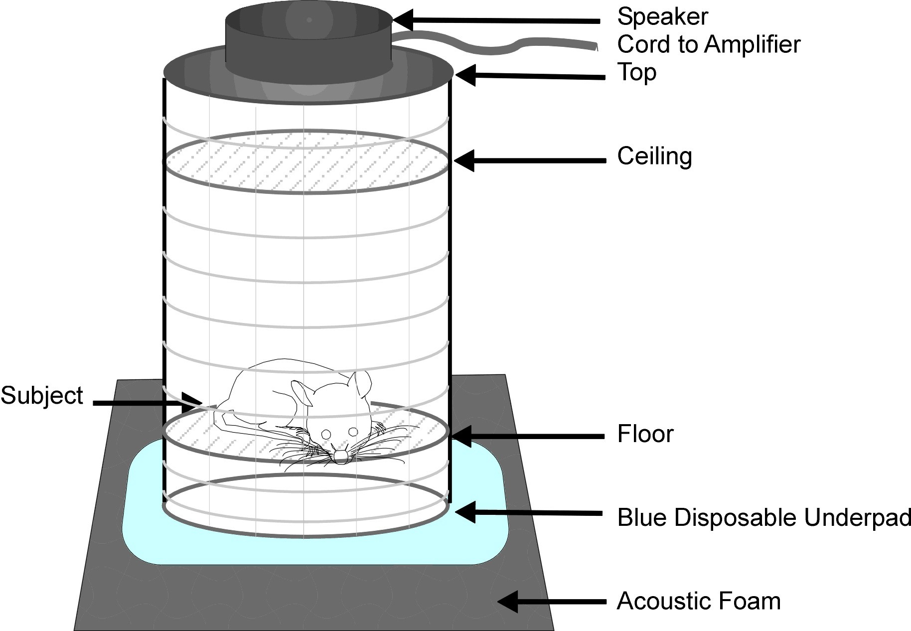 |
| Completed Enclosure with Subject |
Ensure Consistent Signal Delivery
After you build the enclosure, verify that SPL at all test levels or frequencies is even across all spaces in the enclosure.
Working with Multiple Subjects
If you need to expose more than one subject at a time, you can use mesh hardware cloth to divide the tube into four equal size enclosures. The smaller space may also help limit the subject's movements and agitation.
For more than four subjects, add a second tube and speaker in the enclosure and add a second channel to the RPvdsEx circuit file.
To add a second channel:
-
Open the RPvdsEx file.
-
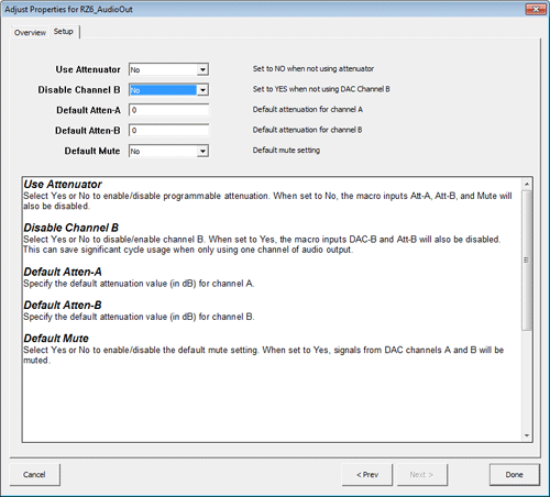
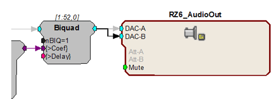
Find the RZ6_AudioOut macro component pictured below. Double-click the component to display the properties.
-
On the Setup tab, change Disable Channel B to No, and click Done.
-
To route the signal to channel B, double-click the teal output port of the Biquad filter that precedes the RZ6_AudioOut then click the teal input port for DAC-B.
-
Be sure to save your changes.
Connect the second output of your RZ6 to a second external amplifier and speaker.