RZ6 Multi I/O Processor
RZ6 Overview
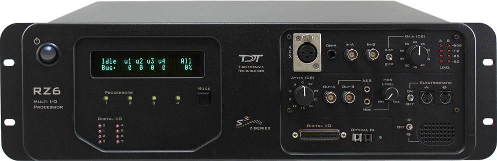
The RZ6 Multi I/O Processor is a high sample rate processor with flexible input/output capabilities. The RZ6 features up to four digital signal processors cards. Any card can be either a single standard processor card (RZDSP) or a quad core processor card (QZDSP). Standard single processor cards use a single Sharc DSP; quad-core processor cards use four Sharc DSPs cores with the potential to more than double the power of the RZ6. All cards are networked on a multiprocessor architecture that features efficient onboard communication and memory access. Two channels each of sigma-delta analog input and output provide a dynamic range of up to 115 dB and sampling rates up to ~200 kHz.
The single device form factor incorporates two channels of onboard programmable and manual attenuation and can drive headphones and standard, magnetic, or electrostatic speakers. It includes an onboard monitor speaker, two channels of amplification for analog inputs, and 24 bits of digital I/O. XLR, audio jack, and BNC connections are supported. Optionally, the RZ6 can be equipped with a fiber optic input, allowing it to support a four channel Medusa preamplifier.
The RZ6-A base version starts with a single DSP and makes an excellent all-in-one psychoacoustics system or can be added to any system to add audio stimulus generation to experiments.
The RZ6-A-P1 comes equipped with four DSPs for more processing power and includes the optional fiber optic input port, allowing it to serve as a BioAmp base station for ABR and OAE studies using TDT's BioSigRZ software.
Both configurations can be upgraded with additional single or quad-core DSP cards (up to a maximum of four DSP cards) for complex filtering and high frequency applications.
Note
RZ6-A-P1 serial number <3000 came with three DSPs in the standard configuration.
Power and Communication
The RZ6's Optibit optical interface connects to a PO5, PO5e, PO5c, or UZ3 computer interface card for fast and reliable data transfer from the RZ2 to the PC. Connectors on the back panel are color coded for correct wiring.
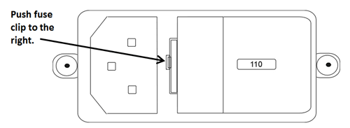
The RZ6's integrated power supply is shipped from TDT configured for the end user's regional voltage setting (110 V or 220 V). If you need to change the voltage setting:
-
Turn off the RZ6
-
Use a small flathead screwdriver to gently push the clip along the left side of the fuse plate to the right to remove it.
-
Remove the white AC voltage selector and rotate it until the desired voltage is displayed, then reinsert it and put the fuse plate back on.
The RZ6 is UL compliant, see the RZ6 Operator's Manual for power and safety information.
Software Control
TDT's Synapse or BioSigRZ software controls the RZ6 and provides users a high level interface for device configuration. If using RPvdsEx to design circuits for the RZ6, see the Legacy System 3 Manual for information on what macros to use.
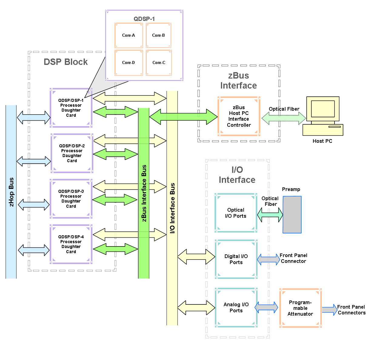
RZ6 Architecture
The RZ6 processor uses a multi-bus architecture and offers three dedicated, data buses for fast, efficient data handling. While the operation of the system architecture is largely transparent to the user, a general understanding is important when designing experiments.
 |
| RZ6 Architecture Diagram |
As shown in the diagram above, the RZ6 architecture consists of three functional blocks:
Bus Related Delays
A standard two sample delay is associated with the zHop. However, these delays are managed for the user in Synapse software.
Functional Signal Flow Diagrams
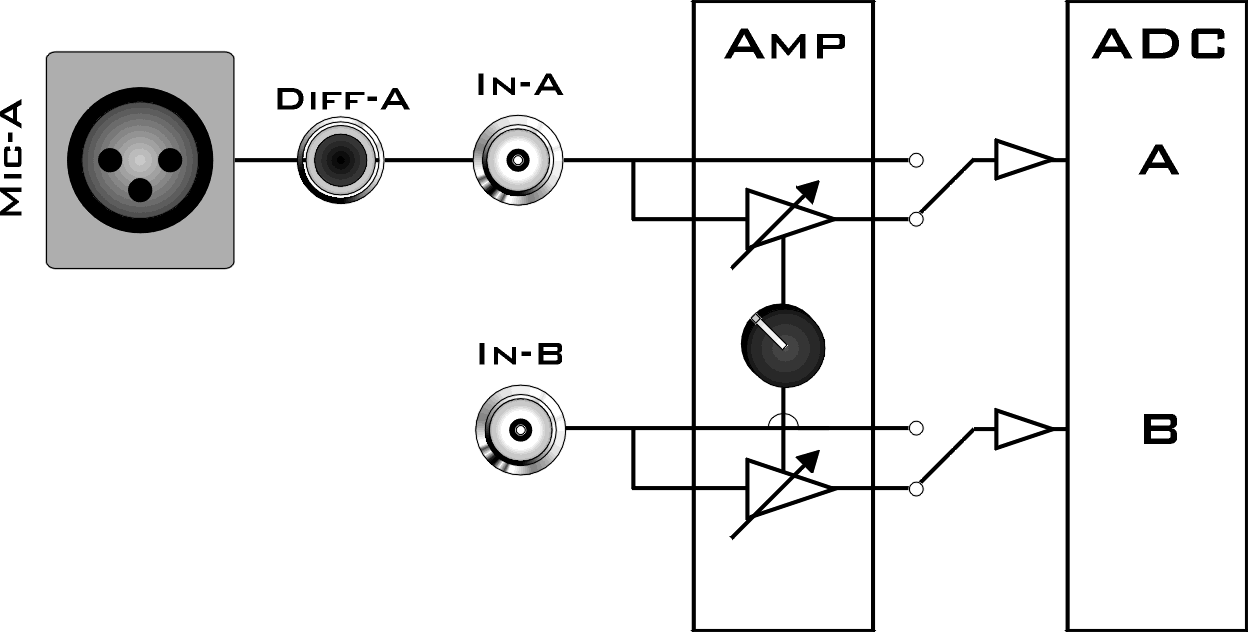
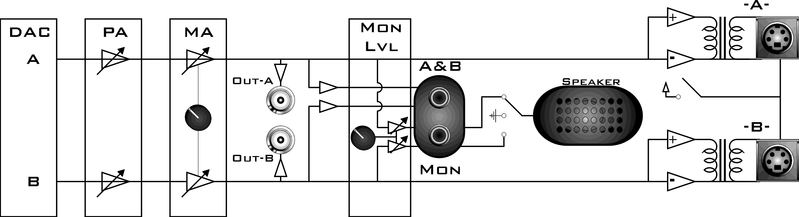
The following diagrams illustrate how analog signals for channels A and B flow through the RZ6 and its modules. For more information on analog input and output see Onboard Analog I/O and Optional Amplifier Input.
 |
| RZ6 Analog Input Flow Diagram |
Input signals for channel A are input either through the XLR input (Mic-A), the audio jack input (Diff-A), or BNC (In-A). Input signals for channel B are input through the BNC (In-B).
A switch located to the left of the gain control knob allows a single gain setting for both channels to be applied or bypassed completely.
 |
| RZ6 Analog Output Flow Diagram |
Signals A and B flow out of the DAC and pass through the programmable and manual attenuation modules prior to being output on the front panel BNC connectors (Out-A and Out-B).
The signals for channels A and B are also passed to two stereo headphone output ports labeled A&B and Mon. Individual stereo power amplifiers are used for the BNC and stereo headphone outputs.
A single channel monitor speaker is connected either to signal A, signal B, or disabled based on the monitor control switch setting. The monitor level knob controls the sound level of both the stereo headphone jack labeled Mon and the monitor speaker.
Finally, if the electrostatic speaker driver is enabled via its switch, located on the front panel, signals A and B are output from the mini-DIN ports located on the RZ6 front panel.
RZ6 Features
DSP Status Lights
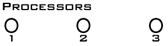
These LEDs report the status of the multiprocessor's individual DSPs and will be lit solid green when the corresponding DSP is installed and running. The corresponding LED will be lit dim green if the cycle usage on a DSP is 0%. If the demands on a DSP exceed 99% of its capacity on any given cycle, the corresponding LED will flash red (~1 time per second). For QZDSPs, the LED indicates levels for the core with the highest cycle usage.
Front Panel Display Screen
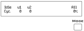
The front panel display screen reports detailed information about the status of the system. The top line reports the system mode, Run!, Idle, or Reset. The second line reports the user's choice of status indicators for each DSP followed by an aggregate value.
The user can cycle through the various status indicators using the Mode button to the bottom right of the display. Push and release the button to change the display or push and hold the button for one second then release to automatically cycle through each of the display options. The display screen may also report system status such as booting status (Reset).
Note
When burning new microcode or if the firmware on the RZ is blank, the display screen will report a cycle usage of 99% and the processor status lights will flash red.
Onboard Analog I/O and Optional Amplifier Input
The RZ6 is equipped with onboard analog I/O and attenuators. It may also include a fiber optic port for Medusa preamplifier input.
The table below provides a quick overview of these I/O features and how they must be accessed during experiment design.
Onboard Analog Inputs
The RZ6 is equipped with two channels of 24-bit sigma-delta A/D converters. See RZ6 Technical Specifications for more information.
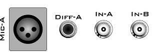
Analog signals can be input through several connectors on the RZ6 front panel.
Channel A has three possible sources:
-
MIC-A (XLR microphone input)
-
DIFF-A (¼" TRS microphone input)
-
BNC labeled In-A
Channel B uses only the BNC labeled In-B:
Important
Use only one input for channel A at a time. Attempting to input signals from multiple sources will produce an erroneous signal.
A and B Microphone Amplifier
An onboard two channel amplifier provides gain for the onboard analog input signals (MIC-A, DIFF-A, In-A, and In-B). The switch located to the left of the gain control knob allows the current gain setting to be applied (if set to Amp) or bypassed completely (if set to Byp).
Important
When the gain is enabled, analog input signals MIC-A and DIFF-A are differential. Since the differential signals are summed a signal gain of 6 dB will be inherently applied. If the amplifier is bypassed, common mode rejection is disabled.
Note
To prevent clipping caused by a DC offset, the amplifier is AC coupled when the gain amplification is in use.
Gain
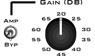
The front panel gain control knob can be used to the control overall signal level of both channels from 20 to 65 dB in 5 dB steps.
Fiber Optic Port - Optional
The RZ6-A-P1 acquires digitized signals from a Medusa preamplifier over a fiber optic cable. The port can be used with the RA4PA or Medusa4Z to input up to 4 channels.
The fiber optic port (devices with serial number 1007 and greater) can also support the HTI3 Head Tracker Interface.
Fiber Oversampling (preamp input)
Signals are digitized on the Medusa preamplifier at a maximum sampling rate of ~25 kHz, however, the fiber optic port on the RZ6 can oversample the digitized signals up to 8X or ~200 kHz. This will allow the RZ6 to run a DSP chain at ~200 kHz and still sample data acquired through an optically connected preamplifier.
Oversampling is performed on the RZ6. The signals being acquired will still be sampled at ~25 kHz on the preamplifier. This means that, even with oversampling, signals acquired by an optically connected preamplifier are still governed by the bandwidth and frequency response of the preamplifier.
Onboard Analog Outputs
The RZ6 is equipped with two channels of 24-bit sigma-delta D/A converters. See RZ6 Technical Specifications for more information. Analog signals are output through a variety of connectors on the RZ6 front panel.
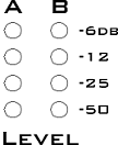
Programmable Attenuation
The RZ6 has two channels of programmable attenuation for precision control of analog output signal levels over a wide dynamic range.
Programmable attenuation in the RZ6 is achieved using both analog and digital attenuation methods. The device supports analog attenuation values of 0, 20, 40, and 60 dB. Attenuation values which lie in-between or exceed 60 dB are handled using digital attenuation.
For example, if you set an attenuation value of 66 dB, the analog attenuator will be set to 60 dB and the remaining 6 dB of attenuation will be applied by scaling the digital signal on the processor before it goes to the DAC.
For the best results, you should use the maximum D/A voltage range and use the attenuators to reduce the output to the target voltage.
Manual Attenuator
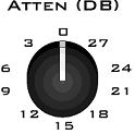
The RZ6 includes another level of analog attenuation that can be controlled manually via the attenuator control knob from 0 to 27 dB in increments of 3 dB.
Manual attenuation is applied to both channels before the signals are output on any of the front panel connectors and is therefore applied in addition to any programmable attenuation.
Analog Output via BNCs

DAC channels A and B are output to BNCs labeled Out-A and Out-B after attenuation has been applied. These outputs use a stereo power amplifier to drive TDT's MF1 multi-function speakers.
A single signal generated or input from any of the RZ6 analog inputs can be ganged to reduce the spectral variation in power of the transducer across all frequencies. To do this, configure your signal to output from both DAC channels and connect your transducer to both channels.
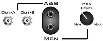
Stereo Headphone Output
DAC channels A and B are also available as a stereo headphone output through two ⅛" audio jack connector ports (channel A is the left stereo output and channel B is the right stereo output). The port labeled A&B (top) provides a stereo headphone output suitable for experimental paradigms while the port labeled Mon (bottom) can be controlled by the Mon Level knob located directly to the right, making it more suitable for monitoring the experiment.
 |
| Audio Outputs |
Note
All outputs use stereo power amplifiers
Monitor Speaker
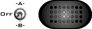
The RZ6 is equipped with an onboard monitor speaker, provided for audio monitoring of a single channel. A switch located directly to the left of the monitor speaker is used to select between DAC channels A and B or to disable the monitor speaker. The monitor speaker output level is controlled by the Mon Level knob located directly to the right of the monitor stereo output.
Electrostatic Speaker Output
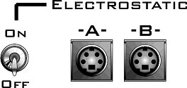
An onboard two channel broadband electrostatic speaker driver is provided, allowing direct connection of TDT's ES series electrostatic speakers. The driver produces flat frequency responses reaching far into the ultrasonic range, can drive two ES series speakers, and is powered using the onboard power supply. A switch located directly to the left of the two 4-pin, mini-DIN connectors is used to enable or disable output of DAC channels A and B.
Note
The electrostatic speaker driver is designed to work exclusively with TDT's electrostatic series speakers. Do NOT attempt to use any other speaker.
Important
If the electrostatic speaker driver is not being used, make sure that the ON/OFF switch is in the OFF position to reduce noise on the RZ6 analog I/O.
Digital I/O
The digital I/O ports include 24 bits of programmable I/O. The digital I/O is divided into three bytes (A, B, and C) as described in the chart below. All digital I/O lines are accessed via the 25-pin connector on the front of the RZ6. Earlier versions (serial number <2000) were limited to 8 bits. See RZ6 Technical Specifications for the DB25 pinout.
The digital I/O is configured in the Synapse RZn Hal.
The data direction for the Digital I/O is also configured in the Synapse RZn Hal, or in RPvdsEx with the RZ6_Control macro.
The RZ digital I/O ports have different voltage outputs and logic thresholds depending on the type. Below is a table listing the different voltage outputs and thresholds for both types.
LED Indicators
The RZ5D has 16 LED indicators for the analog and digital I/O located directly below the display screen and DSP status LEDs.
Digital I/O
These LEDs indicate the state of the 8 bit-addressable I/O of byte C.
Analog Input - ADC LED Indicators
The ADC LED indicators are labeled and located at the top right of the RZ6 front panel. The LEDs indicate the level of the signals on ADC channels A and B. This provides a useful indicator for adjusting the gain and to detect and prevent clipping. The following table describes the LED indicators' operation.
Fiber Optic Indicator
A single green LED indicator next to the fiber optic input port on the RZ6-A-P1 lights when a Medusa preamplifier is correctly synced with the RZ6.
RZ6 Technical Specifications
Note
The RZ6 can be equipped with a fiber optic input port and used with a four channel Medusa preamplifier. See the preamplifier's technical specifications for A/D converters.
Note
For further information on speaker specifications, see ES1/EC1 Technical Specifications and MF1 Technical Specifications.
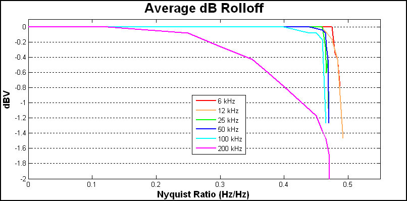
D/A dB Rolloff Diagram
This graph shows the dB rolloff for the RZ6 with varying sampling frequencies for the D/A. The sample delay remains constant for varying frequencies.
DB25 Digital I/O Pinout
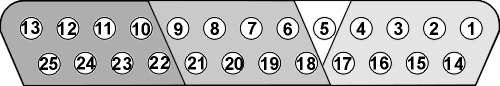
If using a PP24 Patch Panel, see PP24 to RZ6 Digital I/O.