PP24 Patch Panel
Overview
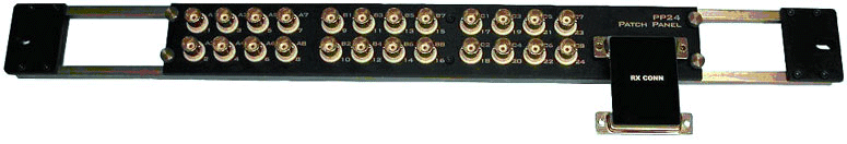
The PP24 Patch Panel provides front panel BNC connections for easy access to the digital and analog inputs and outputs of the RZ and RX processors.
Note
If using the RP2.1 or RA16BA processors, Power Multiplexer (PM2R), or Power Amplifier (SA8), use the PP16 Patch Panel instead.
Adjustable Positioning
The PP24 comes with either an RX CONN or RZ CONN PCB adapter to match your processor type.
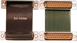
The PP24 has a 25-pin connector on the front panel. The RX CONN PCB Adapter connects the PP24 to an RX device positioned either directly above or directly below the PP24. The RZ CONN connects an RZ processor positioned above the PP24. Loosen the four thumbscrews (one on each corner of the PP24 front panel) to slide the BNC array into the correct position to align the connector with the target device.
Caution
The thumbscrews should never be completely removed. Avoid loosening the thumbscrews too far.
Mapping the Inputs and Outputs for Each Device
The PP24 consists of 3 banks of BNC connectors, Bank A, B, and C. Each of the banks is labeled 1-8 within the set and each BNC is also numbered as part of the entire group from 1 - 24.
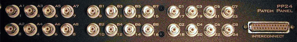
The following table shows the configuration of the BNC connectors for each I/O connector of the RX and RZ devices.
For more information, see the diagrams for the desired device below.
RZ5, RZ5D, RZ5P, RZ6, RZ10x Digital I/O
The PP24 is mounted below the RZ.
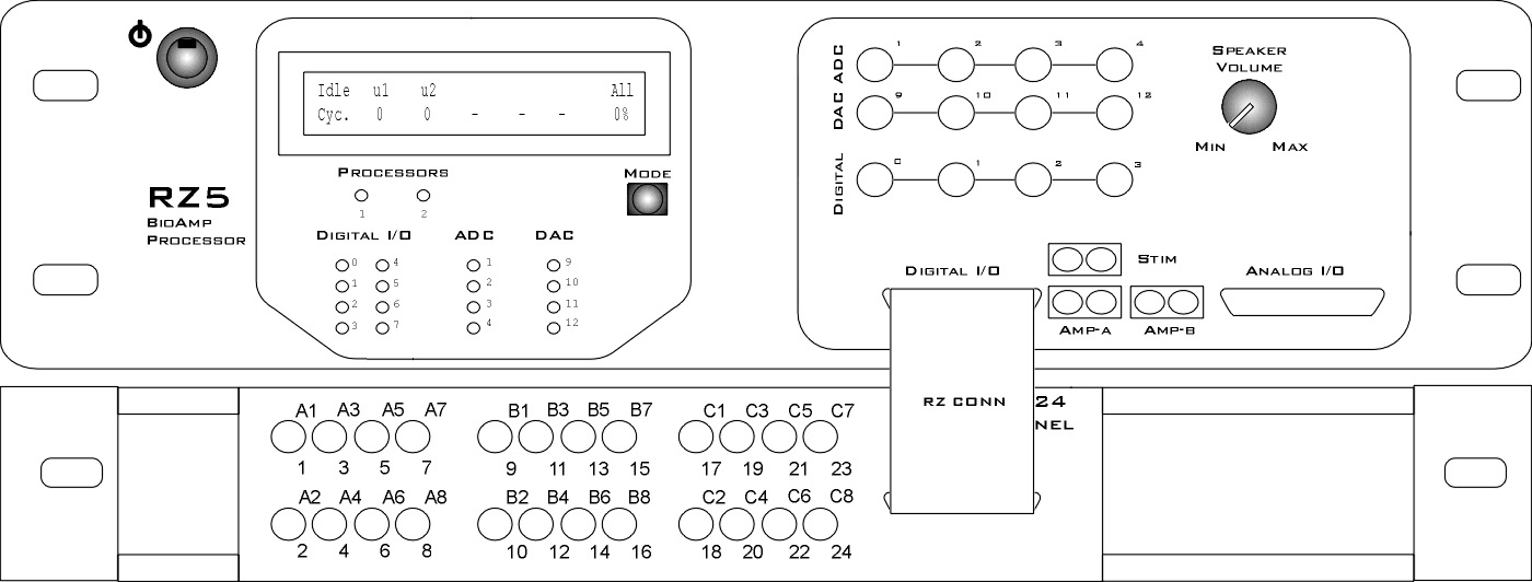 |
| RZ5, RZ5D, RZ5P, RZ6, RZ10x Digital I/O connection to the PP24 |
RZ2 Digital I/O
The PP24 is mounted below the RZ2. Ports A & C are available on the RZ2 front panel BNCs. Port B is only accessible through the DB25 connector.
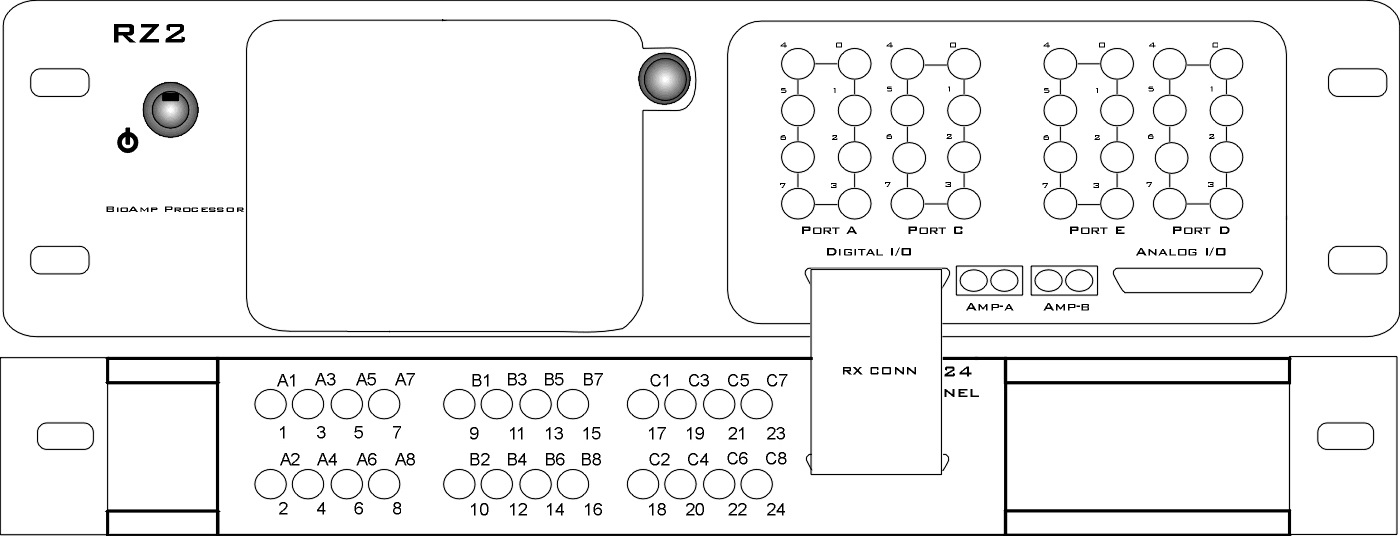 |
| RZ2 Digital I/O connection to the PP24 |
RX5 or RX7 I/O
The PP24 can be mounted above or below the RX5.
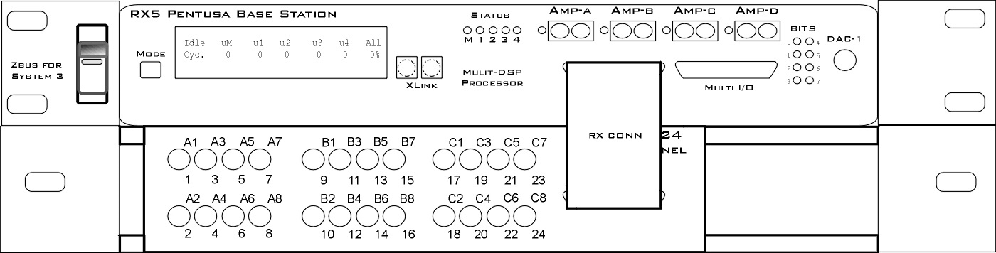 |
| RX5 and RX7 Digital I/O connections to the PP24 |
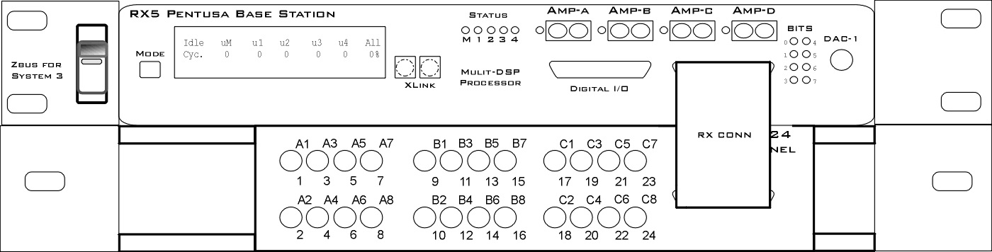 |
| RX5 and RX7 Multi I/O connections to the PP24. |
RX6 Digital I/O
The PP24 can be mounted above or below the RX6.
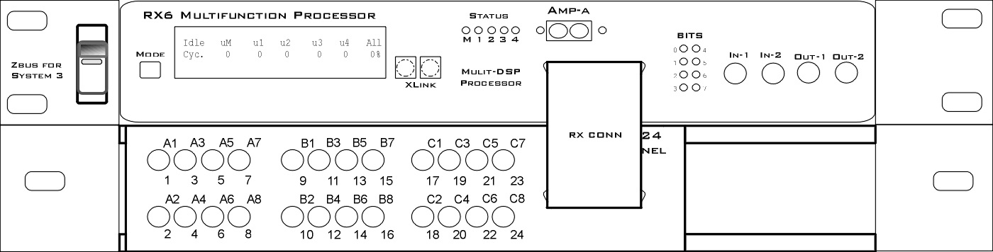 |
| RX6 Digital I/O connection to the PP24 |
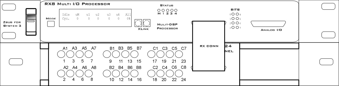
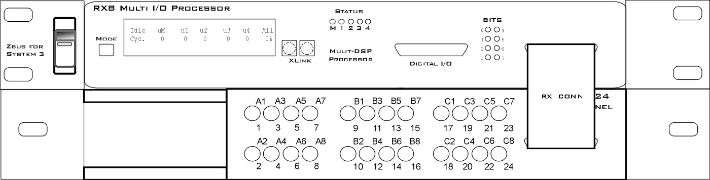
RX8 I/O
The PP24 can be mounted above or below the RX8.
 |
| RX8 Digital I/O connection to the PP24 |
 |
| RX8 Analog I/O connection to the PP24 |