PP16 Patch Panel

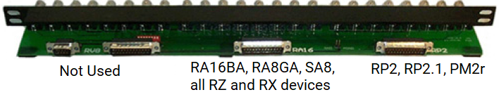
The PP16 Patch Panel provides convenient BNC connections for easy access to the digital and analog inputs and outputs of a variety of System 3 devices. Originally designed for use with the RP2 Real-time Processor, RA16 Medusa Base Station, and RV8 Barracuda; the PP16 back edge is equipped with a nine pin and three 25-pin connectors, which have been marked with the corresponding device label.
To connect the PP16 to a device:
Connect the male end of the 25-pin ribbon cable to the desired module and connect the female end to the correct PP16 input according to the following table.
 |
| PP16 Device Connectors |
PP16 Device Connectors and supported devices:
Mapping the Inputs and Outputs for Each Device
Each device has a unique input and output configuration. The table below shows the configuration of the BNC connectors.
The PP16 can also be used with the RX and RZ devices, however, the PP24 Patch Panel is recommended.
Mapping RA16BA I/O
The diagram below maps the RA16BA Digital I/O connection to the PP16.
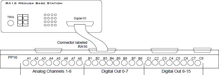 |
| RA16BA to PP16 Connection Diagram |
Mapping RP2/RP2.1 I/O
The diagram below maps the RP2 Digital I/O connection to the PP16. The last seven BNC connectors are not used. BNC C1 maps to VCC 3.3.
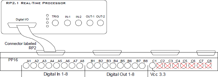 |
| RP2.1 to PP16 Connection Diagram |
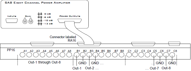
Mapping RA8GA
A PP16 patch panel can be used to simplify connection to the preamplifier's analog inputs. A ribbon cable can be connected from the RA8GA Analog I/O connector to the RA16 connector on the back of the PP16 allowing acquisition of signals via the first eight BNC connectors on the front of the PP16.
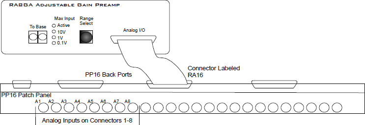 |
| RA8GA to PP16 Connection Diagram |
Mapping PM2R I/O
The diagram below maps the PM2R signal out connection to the PP16.
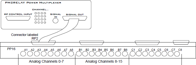 |
| PM2R to PP16 Connection Diagram |
Mapping SA8 Analog Outputs
 |
| SA8 to PP16 Connection Diagram |