PO5/PO5e/PO5c/FO5 Optibit Interface
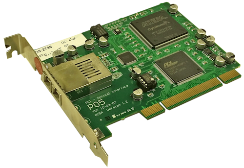 |
| PO5 Interface Card |
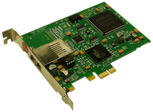 |
| PO5e Interface Card |
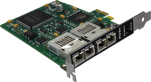 |
| PO5c Interface Card |
Optibit Overview
The Optibit system (Optical Gigabit) is designed for users that require high-speed real-time control of System 3 devices or precise system-wide device synchronization. The Optibit interface consists of a PCI card (PO5), PCIe card (PO5e), or PCI Cluster card (PO5c) that must be installed in the computer and one or more Optibit-to-zBus interface modules (FO5) that mount in the rear slot of a zBus device chassis or is built into RZ Processors. When using the Optibit interface, all devices are automatically phase locked to a single clock.
Part Numbers:
PO5 - Optical PCI Card for Optibit Interface
PO5e - Optical PCI Express Card for Optibit Interface
PO5c - Direct PCI Interface for Cluster Computing
FO5 - Optibit to zBus Interface
Fiber Optic Connection
Devices are connected in a simple loop using provided high speed noise immune fiber optic cabling. See the System 3 Install Guide for installation instructions. For setting up the PO5c card in Synapse, see Cluster Processing with Synapse.
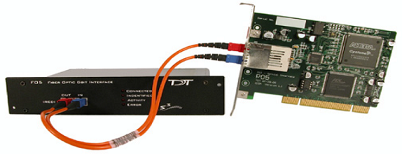
FO5 Status LEDs
Four status LEDs on the face of the FO5 indicate the connection status of the interface.
PO5/PO5e/PO5c Technical Specifications
Interface transfer rates vary by transfer type and device. See Interface Transfer Rates for more information.
Below is a diagram of the compatible PCI and PCIe slots used with the PO5 and PO5e/PO5c Optibit Interface cards.
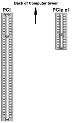
PO5
The PO5 zBus to PC interface card must be installed in a standard size, compliant 3.3 V slot.
PO5e / PO5c
The PO5e and PO5c must be installed in a PCI Express slot. The PO5e card uses a single lane (x1) but may be used in any PCIe slot size (x1, x2, x4, x8 or x16).
Important
Do not attempt to install in low-profile PCI slots. While low profile and standard PCI cards maintain the same electricals, protocols, PC signals, and software drivers as standard PCI expansion cards, the low profile bracket is not compatible with standard card size.
Fiber Optics
Standard cable length is 5 meters. Longer cables (up to 30 meters) are available on request.
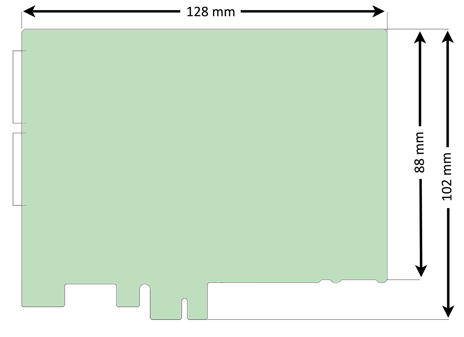 |
| PO5e and PO5c dimensions |
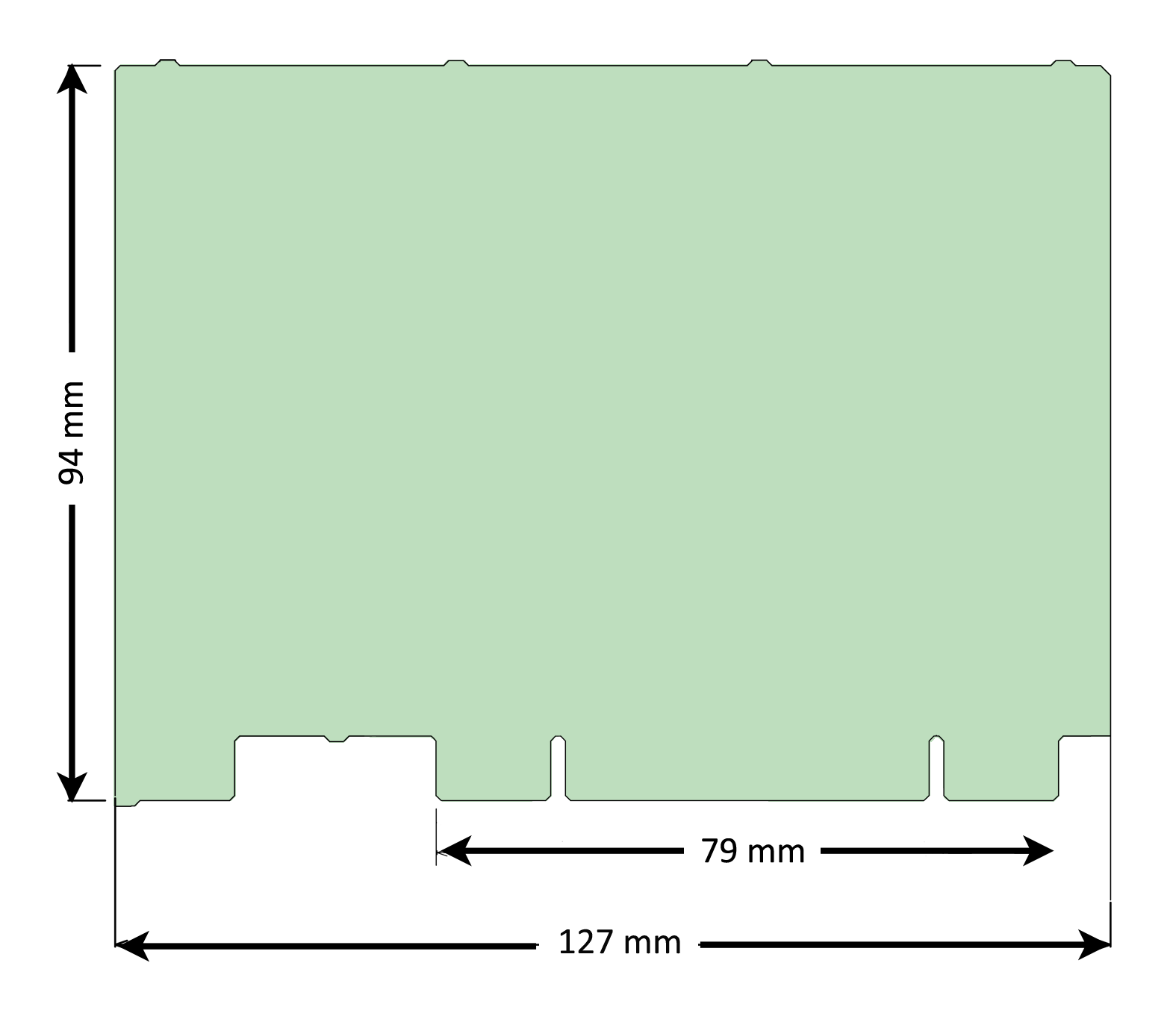 |
| PO5 dimensions |