MF1 Multi-Field Magnetic Speakers
Overview
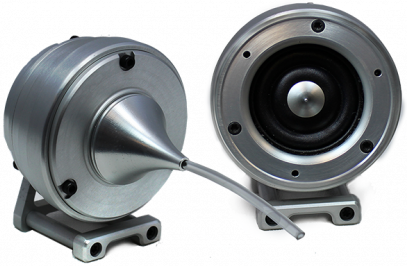
TDT Multi-Field Magnetic Speakers offer high output and fidelity over a wide bandwidth and deliver more power at lower frequencies than our electrostatic speakers. They are well-suited for laboratory species with lower frequency hearing and for noise exposure studies.
A detachable tip allows them to be configured for either free-field or closed-field use. The closed-field configuration uses an internal parabolic cone designed to maximize output and minimize distortion. The tip is tapered to hold ⅛" O.D. PVC tubing. The mono speaker comes with two 10 cm tubes and the dual speaker set comes with four 10 cm tubes.
Note
An Ear Tip for direct application (no tubing required), is also available.
Speakers feature a rugged aluminum housing and a built-in, 8-32 threaded hole for standard laboratory mounting hardware. The mono speaker includes an aluminum stand and the dual speaker set includes a variety of aluminum mount/base fittings for easier positioning.
Each MF1 kit (serial number >1200) also includes a USB drive containing several
speaker-specific closed field and free field calibration curves (TCF files) made
during final testing at TDT. These files are used with the BioSigRZ software.
When using the MF1 speakers above 30 kHz in free field mode,
TDT recommends using the speaker-specific TCF files in place of the generic
speaker curves provided in the BioSigRZ installation (stored by default in
C:\TDT\BioSigRZ\TCF\).
The speakers can be driven directly from the RZ6 or using TDT's SA1 or SA8 stereo amplifiers.
Part Numbers:
MF1-M - Mono, single speaker
MF1-S - Stereo, two speakers
Multi-Field Configurations
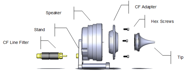
The MF1 speaker consists of the free-field speaker and a closed-field adapter - a tapered tip and line filter for closed-field use. An RCA to BNC adapter and stand are also provided.
Using the MF1 for Free Field Operation
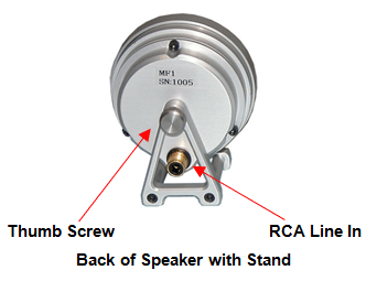
The MF1 main speaker component can be used for free-field sound production. The speaker can be connected to the source via an RCA connector located on the back of the MF1 housing. If using the stereo amplifier built into the RZ6, simply connect the supplied RCA cable from the MF1 to one of the output BNC connectors on the RZ6 using the supplied RCA to BNC adapter.
Caution
When the speaker is configured for free field use, be careful to avoid touching the exposed speaker membrane.
Configuring the MF1 for Closed Field Operation
For closed-field operation, the Close Field adapter is attached to the face of the speaker using three hex screws. A parabolic tip is be mounted in the recessed socket on the closed-field adapter and is held securely in place by an o-ring at the base of the tip.
The speaker can be connected to the source via an RCA connector located on the back of the MF1 housing. If using the stereo amplifier built into the RZ6, simply connect the supplied RCA cable from the MF1 to one of the output BNC connectors on the RZ6 using the supplied RCA to BNC adapters.
Important
When using the MF1 in the closed-field configuration the supplied CF line filter must be installed between the BNC to RCA adapter and the RCA cable. This filter minimizes distortion at lower frequencies in the closed-field.
To configure the MF1 for closed-field:
-
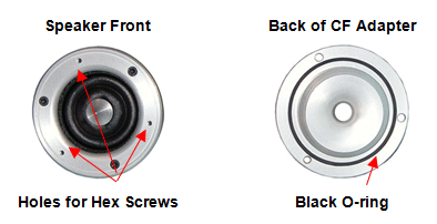
Ensure black o-ring is in place on back of CF adapter, as shown.
Attach the CF adapter to the front of the speaker using three of the provided ¼ x 4-40 hex screws.
-
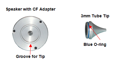
Ensure the blue o-ring is in place at the base of the desired tip, as shown.
-
Insert one of the tips into the groove on the CF adapter. Ensure the tip is bottomed in its socket. If using the tube tip, gently insert the tube into the narrow end of the tip.
-
Attach a BNC to RCA adapter to the BNC amplifier port of your source device.
Attach the CF filter to the RCA cable.

CF Filter For Closed Field Configuration Only
If desired, the provided stand can be attached to the speaker using a thumbscrew.
- Connect the MF1 to the amplifier using the RCA cable (with CF filter attached).
Closed-Field Speaker Design Considerations
When using the closed-field configuration for experiments, the provided PVC tubing will transfer the signal best when it is kept straight. Note that the speaker performance is dependent on the coupling system used and the ear of the subject. All speaker configurations should be calibrated to your specific configuration. Technical specifications measured under specific controlled conditions are provided for comparison purposes. If using BioSigRZ software, see the ABR Guide or DPOAE Guide for calibration tips.
MF1 Technical Specifications
* Available on request.
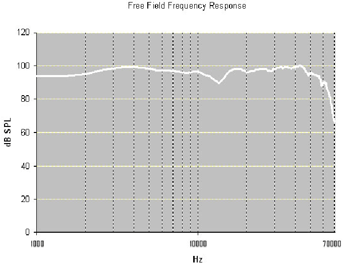 |
| Free field measurements typical at 10 cm using ±1 V input |
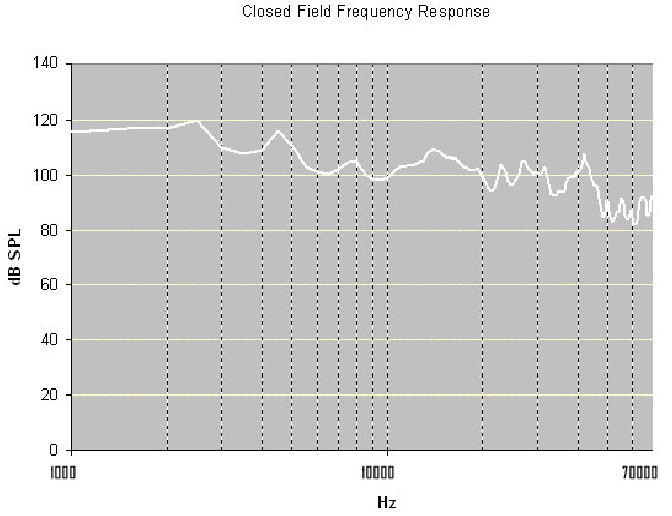 |
| Closed field measurements typical for approx 0.1 cc eartip coupler using ±1 V input |