EC1/ES1 Electrostatic Speaker
Overview
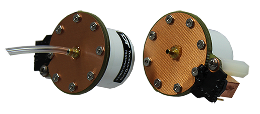
TDT Electrostatic Speakers (Patent No. US 6,842,964 B1) are designed specifically for ultrasonic signal production. The electrostatic design offers a thin, flexible membrane with an extremely low moving mass. Unlike conventional speakers, these speakers distribute the driving signal homogeneously over the surface of the membrane. These factors produce a small, lightweight speaker with an excellent ultrasonic response and very low distortion. Available with or without a coupler, both models are easy to position and are particularly well suited for studies with small animals that have hearing in the ultrasonic range.
Part Numbers (Patent No. US 6,842,964 B1):
ES1 - Free Field Electrostatic Speaker
EC1 - Electrostatic Speaker-Coupler Model
Cable Connection
The ES1 and EC1 electrostatic speakers work exclusively with the ED1 Electrostatic Speaker Driver. Input is via a 4-pin, mini-DIN connector, which carries both bias and signal voltages from the speaker driver. Connection to the speaker driver is through a standard 6.1 m long cable. Other cable lengths can be special ordered, but will affect the speaker's frequency response. The speakers come fully enclosed to eliminate access to the high-voltage bias and driving signals. A 3.175 mm mounting hole at the base of the speaker accepts a standard 4-40 standoff. See ED1 Electrostatic Speaker Driver for information about gain settings.
The orientation of the cable connection is indicated with dots on the cable connector and on the speaker. The cable should be connected so that the dot on the cable faces towards the speaker.
When connecting the cable, ensure that the four pin connectors are fully seated on the speaker and the speaker driver. When the cable is repeatedly moved during the experiment, periodically check that the connectors are fully seated.
EC1 Coupled Electrostatic Speaker
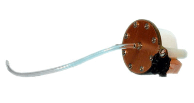
The EC1 includes a small piece of ⅛" O.D. Tygon tubing coupled to the output. The tubing will transfer the signal best when it is kept straight. Note that the speaker performance is dependent on the coupling system used and the ear of the animal. Users should test the device under experimental conditions to ensure it meets their requirements. If using BioSigRZ software, see the ABR Guide or DPOAE Guide for calibration tips. Technical Specifications measured under specific controlled conditions are provided for comparison purposes.
Maximizing the Life of the Speakers
The TDT electrostatic speakers are designed to operate with input signals between 4 kHz and 110 kHz. Playing signals below 4 kHz causes a large amount of harmonic distortion that degrades the operation of the speakers over time, causing a decreased power output across all frequencies. Although the speakers won't clip until ±10 V, presenting continual input voltage over ±4 V will reduce speaker lifespan.
Broadband Signals
When using broadband signals, limit the amount of energy in the low frequency ranges whenever possible. For example, band-limiting noise stimuli with a high pass filter at 4 kHz or above (the higher the better for the life of the speakers) and limiting complex harmonic signals, such as frequency sweeps, to frequencies above 4 kHz can increase the effective life of the speakers.
Click Stimuli
ABR experiments in both human and mouse studies typically use a 100 microsecond click stimuli, which has most of its energy in the 2 kHz to 8 kHz range. Because click stimuli are short impulses that generate signals across a broad frequency range, band limiting the frequencies is not feasible. TDT recommends that users attenuate the click stimuli so as to minimize the potential effects on the speaker. Also note that the shorter the stimuli the flatter the frequency response and the greater the energy in the higher frequencies. Moreover, the shorter the duration of the click the less total energy it has (for a given voltage).
Routine Care and Maintenance
Inspect speakers for visual damage or obstruction of the speaker holes prior to use. If there is damage to the copper shield around the components next to the connector or debris clogging the speaker holes, contact TDT for an RMA for repair.
Caution
NEVER attempt to clean the holes in the baseplate of the speaker. Doing so can puncture the speaker membrane.
When using the EC1, check the end of the Tygon tubing for cerumen and other debris and clean as necessary.
ES1 Technical Specifications
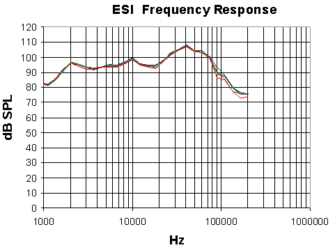 |
| Free-field Frequency Response of Four Speakers at 10 cm |
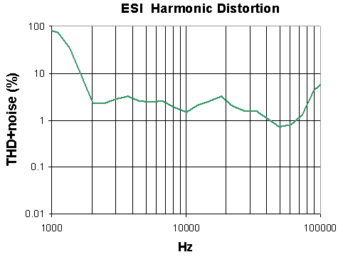 |
| Harmonic Distortion at 4 V Peak |
Noise as well as harmonic distortion is measured. Lower signal levels (e.g. above 75 kHz shown above) have higher THD+noise because of lower signal to noise ratios. When measured at higher signal levels, the THD above 75 kHz is actually <3% up to 110 kHz.
EC1 Technical Specifications
Frequency Response in Plexiglas Coupler
*Measurements were made in a 1 cm x 0.5 cm coupler with a 20 cm length of 2.4 mm i.e. tubing attached to the fitting of the EC1. 4 V peak input tones were tested and frequency response was measured with a calibrated pressure microphone.
The results of the calibration will vary depending on the type of ear to which the speaker is coupled and the length of the tube that is coupled to the ear. This curve is provided as representative of the type of response that may be obtained in a closed field.
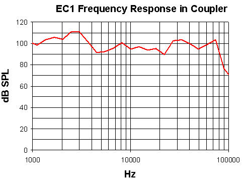
In this case, the low end of the response (<5 kHz) is enhanced over the free- field response while the high end of the response (>80 kHz) is attenuated.
Every experimental setup is unique. It is important to calibrate the response of the speaker in each experimental setup.
Important
Modifying the EC1 or ES1 can result in unexpected changes in the transfer function. All modifications to the EC1 or ES1 should be performed by TDT. If you need to be 30-60 dB lower than specifications, or if you have one of these devices, contact TDT for assistance.