Test Your System
The zBUSmon utility is used to test the connection between the computer and your processors. When all devices are connected correctly, open the zBUSmon program.
To open zBUSmon, click the zBUSmon shortcut on the Desktop. Alternatively, click the Start button on the Windows taskbar, point to Programs, point to TDT Sys3, and click zBUSmon.
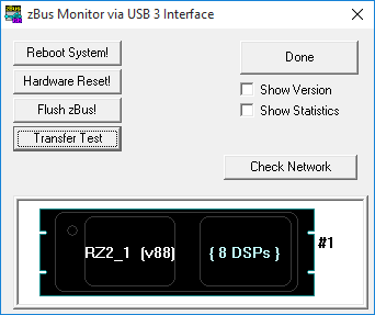
This program allows you to test the connection from the PC to the System 3 hardware. The hardware diagram displays all zBus chassis and programmable devices, such as the RZ2, RX6, RP2.1, and PA5, connected to the PC.
The hardware diagram will not show non-programmable devices, such as the HB7, SM5, SA1, SA8, ED1, MA3, PM2r, FD1, or MS2. It also won't show peripheral devices that connect directly to the RZ processors, such as the PZ5 or IZ2. However, non-programmable devices that require a connection to the PC, such as the RA8GA and HTI3, will appear as an empty zBus chassis.
What zBUSmon Shows You
Microcode. The microcode version of each processor device is shown in parentheses after the device type and index. If you have an RZ device in your configuration, the number of DSPs installed on that RZ device will also be displayed.
The microcode running on each processor should match the driver version number. The device name of any device programmed with outdated microcode will appear in red in the diagram. If you update your TDT drivers in the future, you must also manually update the microcode for each of your real-time processors. See Updating Your System.
Note that the interface version number (v10 or v15) is fixed and cannot be changed by the user. The microcode on the PA5 programmable attenuators (v30) is also fixed.
Logical index. The programmable devices are given a logical index starting with 1 so that multiple devices of the same type can be distinguished in software. This is the number in the device name after the underscore. The logical number of the zBus chassis, displayed to the right of the chassis, reflects the order of the connections between chassis.
Show Version. When the Show Version check box is selected, the microcode version of the interface and of each programmable device is displayed.
Statistics. When the Show Statistics box is checked, the amount of data transferred from the TDT System 3 modules to the PC and from the PC to the TDT System 3 modules, and the error status, are displayed. If you see an error value other than 0, click Hardware Reset! to reset all connected hardware.
Run a Transfer Test
A Transfer Test can be used to test data transfer both to and from the PC.
- Ensure the Show Statistics check box is selected.
- Click the Transfer Test button in zBUSmon.
If successful, you will see a Test Passed message. The amount of data transferred to and from the PC will be displayed with no errors.
Now that your system is set up and functioning, you can connect the rest of the system components, such as preamplifiers, video trackers, and data streamers. See Connecting Peripherals to the RZ for devices that attach to the processor, and the System 3 Manual for everything else.
Cluster Computing
If you are setting up a system for cluster computing, combining several WS8 + System 3 devices into a synchronized system, set up the individual systems first, then connect them as shown in the Synapse Manual, Cluster Processing chapter.
In zBUSmon, cluster information is displayed when you select Show Version.
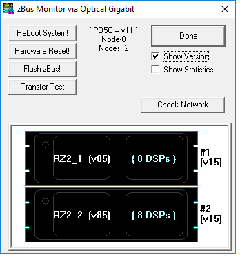
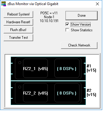
If the PO5c card is set to Parent, "Node 0" is displayed along with the number of nodes (WS8s) connected. If the PO5c is set to Child, the node position in the cluster (1+) is displayed along with the IP address of the connected Parent node. See the Synapse Manual for more information.
Testing a Legacy UZ2 USB Interface
When all devices are connected correctly, run the zBUSmon program. Double-click the zBUSmon shortcut that installs to the Desktop, or click the Start button on the Windows taskbar, point to Programs, point to TDT Sys3, and click zBUSmon.
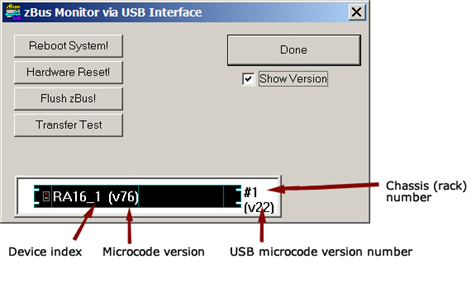
This program allows you to test the USB connection from the PC to the System 3 hardware. The hardware diagram displays all zBus chassis and programmable devices, such as the RP2.1, RX6 and PA5. The hardware diagram will not show most non-programmable devices, such as the HB7 or SM5; however, non-programmable devices that require a connection to the PC (for example RA8GA, HTI3) will appear as an empty zBus chassis.
Power devices on in the same order every time
The device indices are dependent on the order in which the devices were powered on and recognized by the PC. Software applications connect to the devices by name and index value. If you have multiple devices of the same type it is very important that you power on the devices in the same order every time so that the device indices will be consistent in software. The number of the zBus chassis, displayed to the right of the chassis in the diagram, reflects the order in which the USB devices were powered on.
The microcode version of all real-time processors (RXn, RPx and so forth) is displayed in parentheses to the right of the part number in the diagram. They must match the current version of TDT Drivers installed on the PC. If you installed the drivers that came with your system, then your devices were preprogrammed with the correct microcode.
Note that the USB microcode version number (v22) is fixed and cannot be changed by the user. The microcode on the PA5 programmable attenuators (v30) is also fixed.
After a hardware reset
When using the UZ2 USB 2.0 interfaces, clicking the Hardware Reset button in zBUSmon will change the version numbers to 6543 and a transfer test will fail. After using the Hardware Reset button, wait 20 seconds then close and reopen zBUSmon. The correct version numbers should be displayed.