Setting Up with a PCI Card or UZ3
System 3 is a flexible platform. Part of that flexibility is the ability to interface with a user-selected, Windows-based desktop or laptop computer. Before you begin setting up your system, you'll need to determine what type of interface your system uses and check your PC to ensure it meets the requirements for TDT software and your interface.
This page covers the two Optibit interfaces, which both drive the same fiber optic chain:
- PO5e / PO5c: a PCI Express card installed in a desktop computer.
- UZ3: a version of the Optibit interface that connects to a laptop or PC via USB 3.0, with no card to install.
Steps
- Unpack your equipment and identify your system interface, components and connection cables. See Identify Your Processors and Interface.
- Install the TDT Drivers on your computer.
- Install the interface card in your PC (PO5e and PO5c only).
- Connect your computer to the processor(s).
- Power on the system.
- Test the system.
Install the drivers first
The interface type must be selected during driver installation, and TDT Drivers must be installed before connecting any TDT hardware to your PC. See Install the TDT Drivers.
Install the PCI Card in the Computer
Desktop-based systems using the Optibit interface (built into the RZ processor and/or FO5 zBus modules pre-installed in the ZB1PS device chassis) ship with fiber optic connector cables and a PCI Express (PO5e or PO5c) card. Cables might include a 5-meter duplex cable to connect the PO5e/PO5c to the TDT modules, and possibly one or more 30 cm cables to connect multiple TDT chassis. Before connecting the rest of your system, you must install the interface card in your computer.
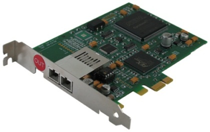
PO5e
Turn the computer off first
To prevent damage to the PO5e/PO5c card and computer, turn off the computer before installing the card. Leave the computer plugged into a surge strip or battery backup so that it remains grounded.
- Turn off the PC and open the cover.
-
Install the interface card. The diagram below shows compatible PCIe slots used with the PO5e and PO5c Optibit Interface cards.
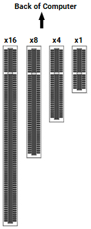
The PO5e and PO5c cards use a single lane (x1) but may be used in any PCIe slot size (x1, x4, x8 or x16).
Not low-profile slots
Do not attempt to install in low-profile PCI slots. While low profile and standard cards maintain the same electrical protocols, PC signals, and software, the low-profile bracket is not compatible with standard cards.
-
Reconnect hardware devices such as a monitor, mouse, and keyboard, as needed.
- Restart the PC.
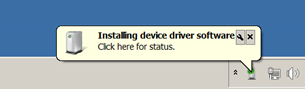
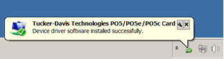
Windows will automatically detect the PO5e/PO5c card and install the drivers. Message balloons will be displayed during this process.
Note
On 64-bit operating systems the card will be identified as Tucker-Davis Technologies PO5 Card (64-bit driver).
If the PO5e/PO5c card is not detected automatically, you can scan for new hardware in the Device Manager or contact TDT support for assistance.
When the driver installation is complete, continue to Assemble the zBus Chassis with Optibit Interface.
Connect to the UZ3 Optibit Interface
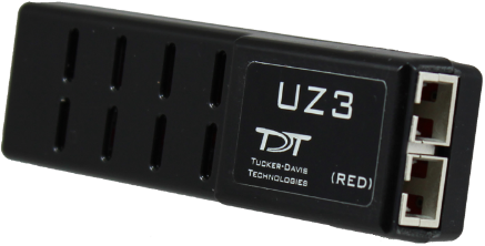
Laptop-based systems (or any system using a USB 3.0 interface) with TDT processors using the Optibit interface (FO5 zBus modules pre-installed in the ZB1PS device chassis and/or built into the RZ processor) ship with fiber optic connector cables, a UZ3 interface adapter, a USB C-C cable, and a C-A adapter.
Connect the UZ3 to your laptop/PC USB 3.0 port. Windows should automatically install the driver for it. Once the driver installation is complete, you can connect the UZ3 interface to the RZ or FO5 modules in the zBus device chassis. See Assemble the zBus Chassis with Optibit Interface.
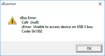
If the drivers failed to install correctly, or the UZ3 is not connected properly, the following error message will appear when you open zBUSmon:
Assemble the zBus Chassis with Optibit Interface
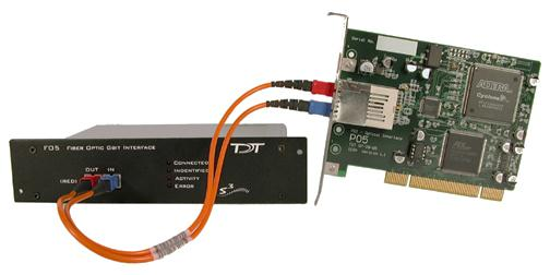
The RZ or zBus chassis (racks) connect to the PO5/PO5e/PO5c/UZ3 through the Optibit interface to form a communication loop between the PC and the TDT hardware. With the RZ, access to the Optibit interface is found on the back panel. In a zBus chassis, the Optibit interface is an FO5 module mounted in a rear bay.
Be sure to remove the clear plastic protective plugs from the ends of the cables first. The fiber-optic cables have raised keys on one side of the connector. There are also keyway notches on the inside of the connectors on the RZ or FO5 module and the PO5/PO5e/PO5c/UZ3 interface. The fiber-optic cable should be oriented so that the keys on the cable connectors line up with the keyway notches on the modules.
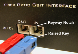
When connecting the fiber optic cable, grasp the cable by the cap and push firmly. You will hear a click when the cable is connected securely. When disconnecting, grasp the cap and pull straight out. You will first notice the cap sliding backward slightly. This unlocks the cable and allows it to be removed. This locking connection prevents accidental disconnects.
To Connect One Optibit Interface
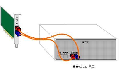
- Connect the red end of a 5-meter cable to the output of the PO5/PO5e/PO5c/UZ3. The PO5/PO5e/PO5c is marked with a red dot labeled OUT. The UZ3 has the text (RED).
- Connect the other end of this cable (blue) to the input on the Optibit interface (labeled IN).
- Connect the red end of the second 5-meter cable to the output of the Optibit interface (labeled OUT).
- Connect the other end of the second cable to the input of the PO5/PO5e/PO5c/UZ3 (not labeled).
To Connect Multiple Optibit Interfaces
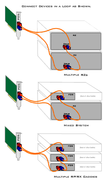
- Connect the red end of a 5-meter cable to the output of the PO5/PO5e/PO5c/UZ3 (marked with a red dot labeled OUT).
- Connect the other end of this cable (blue) to the input on the first Optibit interface (labeled IN).
- Connect the red end of a 30 cm cable to the output of the first Optibit interface (labeled OUT).
- Connect the other end of the first 30 cm cable (blue) to the input on the second Optibit interface (labeled IN).
- Repeat with 30 cm cables for each additional Optibit interface.
- Connect the red end of the second 5-meter cable to the output of the last Optibit interface (labeled OUT).
- Connect the other end of this cable (blue) to the input on the PO5/PO5e/PO5c/UZ3 (not labeled).
Power On the Optibit System
To test the Optibit interface, turn on the PC, plug the RZ or zBus device chassis power cable(s) into a surge strip or battery backup, then power on. The zBus chassis can be powered on in any order.
The RZ devices have a blue indicator light to show that the device is powered on. The RZ2 LCD screen will display interface connection information; other RZ devices do not display this information.
Once a zBus chassis is powered on, the green indicator light on the power switch will flash regularly (~1 Hz) until communication is initiated by TDT software, such as zBUSmon, RPvdsEx or OpenEx. After this initial communication, the green indicator light will glow steadily. You will also notice the green indicator light pulsing when data is being transferred to or from the zBus chassis.
Next Steps
- Test Your System: confirm the PC can talk to your processors with zBUSmon.
- After Setting Up Your System: documentation, warranty, and where to get more help.