Setting Up with a TDT Workstation
The WS computer workstation is rack-mountable and purpose-built for TDT System 3 and your demanding research applications. It's shipped with your TDT software and an Optibit TDT interface card pre-installed to make setting up your system as streamlined as possible.
Drivers are already installed
Because the WS ships with TDT software and the Optibit card already installed, you can skip Install the TDT Drivers entirely and go straight to connecting your hardware.
Steps
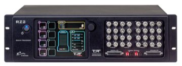
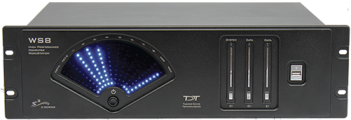
- Unpack your equipment, identify your system components.
- Connect the WS keyboard, mouse, and monitor(s).
- Power on the WS and monitor(s).
- Connect the fiber optic interface between the WS and processor.
- Power on the processor.
- Test the system.
The rest of this page covers each step in more detail with step-by-step instructions and illustrations.
Identify Your Processors and Interface-Dependent Devices
You will only need to identify your processors and other interface devices that must be directly in the communications interface loop with the PC. See Identify Your Processors and Interface for the full rundown of form factors.
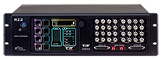

If your system includes more than one processor/attenuator, you must interconnect (daisy-chain) them during setup.
Connect the WS Input/Output Peripherals
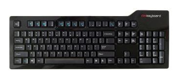
Keyboard and Mouse. The WS is supplied with a keyboard and optical mouse. USB connections are provided on the WS back panel and two 10 ft. USB extension cables are provided to allow the WS to be rack-mounted with other equipment while the mouse and keyboard are positioned in a nearby work area.
Monitors.
- WS8: a high-performance video card supports up to three monitors.
- WS4: a high-quality video card supports two monitors.
Note
While there are alternate video connectors on the back panel (DP, VGA, DVI-D), they are disabled.
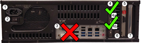
Back Panel Connections:
- AC Power Cord Input
- Power Supply On/Off Switch
- USB Inputs, used for provided Mouse and Keyboard
- Video Card with DVI, HDMI, or mini-Display port outputs
- PO5e Optical Card
- Unavailable
- Open PCIe x4, Half-Length Slot
Power On the WS
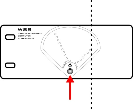
The power supply is auto-switching for 110 V or 220 V. A soft on/off button is provided on the front panel and a hard power cutoff switch is provided on the back panel.
-
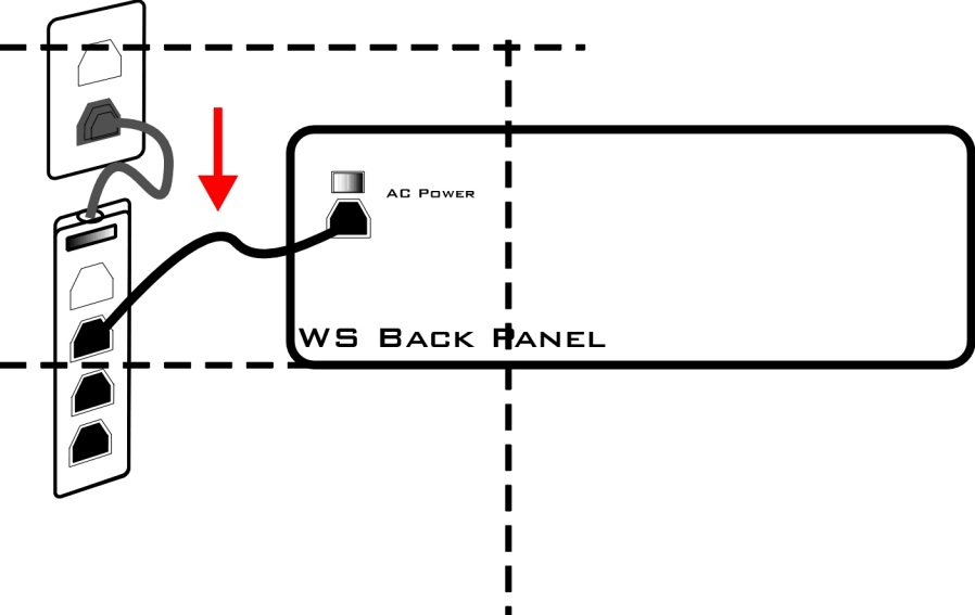
Use the provided AC power cord to connect the WS to a power strip or battery back-up connected to mains power.
-
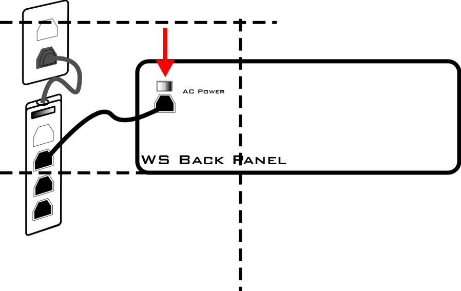
Use the back panel power switch to power on the WS.
-
Use the front panel power button to start the device.
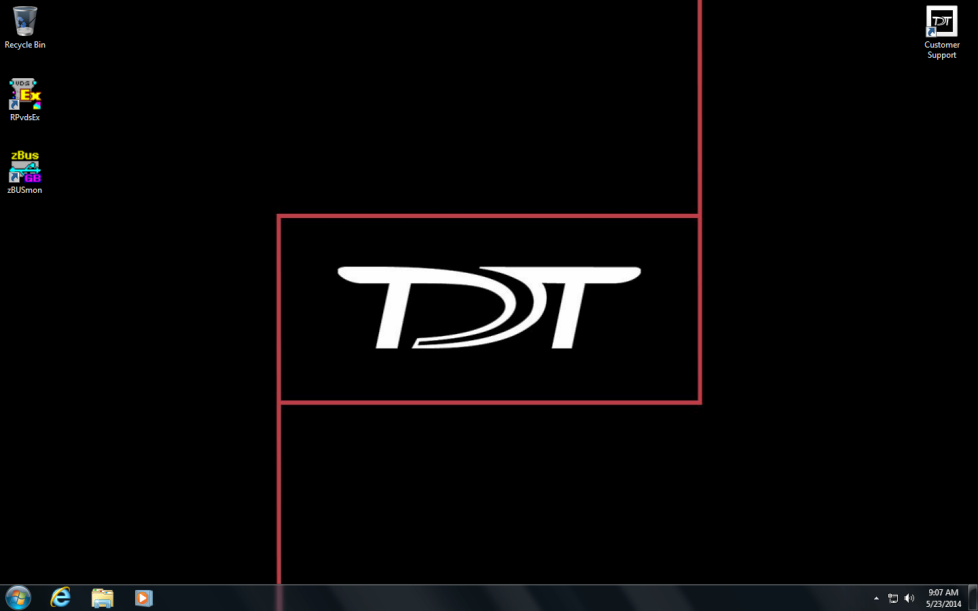
The WS is shipped with the 64-bit Windows 11 operating system. When Windows launches, you can set up user accounts and customize your desktop as you would with any computer. Your TDT software has already been installed and is available from the Start menu or on your desktop. Your desktop includes a link to the zBUSmon utility that you will use later and a shortcut to our online support page.
Connect the WS Optical Interface
Processors and other interface-dependent devices mounted in a zBus chassis (rack) must connect to the WS's Optibit interface to form a communication loop between the PC and the TDT hardware.
Use the provided fiber optic cables to make the connections described below. Be sure to remove the clear plastic protective plugs from the ends of the cables first.
Use the provided duplex fiber optic patch cables (orange) to connect the WS's factory-installed Optibit optical interface card to the processor(s). The fiber optic ports on each device and the patch cables are color-coded and use key and notch connectors to ensure correct wiring.
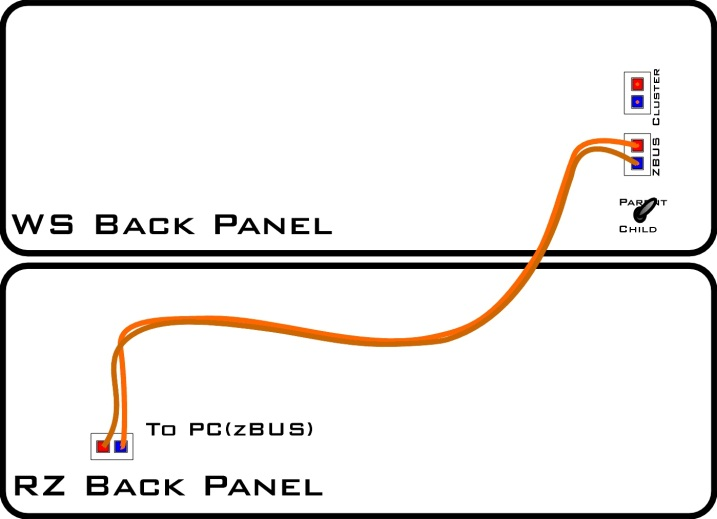
Connecting the WS to a Single RZ Device
-
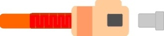
Remove the protective caps covering the ferrules on the fiber optic patch cable and fiber optic ports.
-
Connect one end of the duplex cable to the fiber optic port on the WS's factory-installed, Optibit optical interface card.
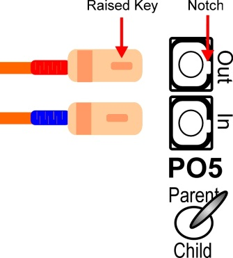
- Match the strand with a red collar to the Out port connector as shown.
- Line up the raised key on the boot with the keyway notch on the interface port connector.
- Grasp the strand by the boot and push the end firmly into the port. You will hear a click when the strand is connected securely.
Disconnecting
Grasp the boot and pull straight out. You will first notice the connector sliding backward slightly. This unlocks the strand and allows it to be removed. This locking connection prevents accidental disconnects.
-
If your interface card has a Parent/Child switch, set it to Parent. Child is only used for Cluster Computing.
-
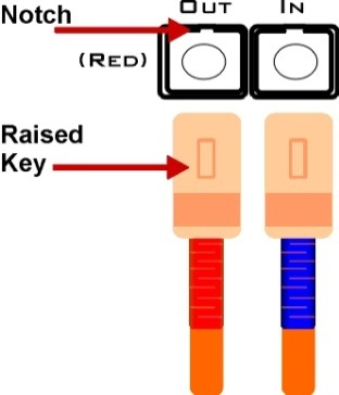
Connect the strand with the blue collar to the In connector on the port.
- Repeat the steps to connect the other end of the duplex cable to the To PC (zBus) port on the processor's back panel.
Connecting Multiple Devices
Multiple processors (or other interface-dependent devices mounted in a zBus chassis) can be connected to the WS's Optibit interface. See the connection diagrams below for common configurations.
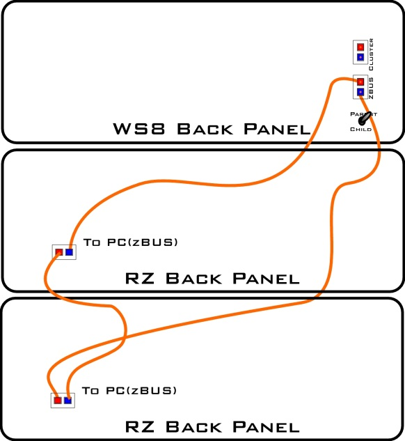
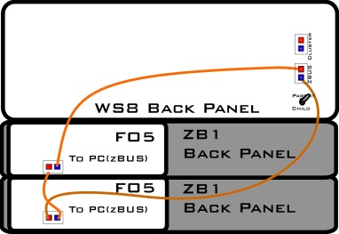
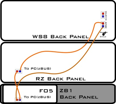
Mixed RZ and RX or RP2.1 Processors
-
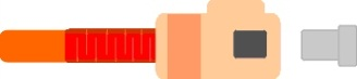
Remove the protective caps covering the ferrules on the patch cable and fiber optic ports.
-
Connect the end of a single strand 5-meter cable to the fiber optic port on the WS's factory-installed Optibit optical interface card.
Note
The strands of the supplied 5-meter duplex patch cables pull apart for simplex use.
-
Match the strand with a red collar to the Out port connector as shown.
-
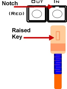
Line up the raised key on the boot with the keyway notch on the interface connector.
- Grasp the strand by the boot and push the end firmly into the port. You will hear a click when the strand is connected securely.
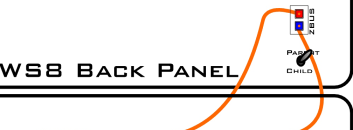
- Set the Parent/Child switch to Parent. Child is only used for Synapse Cluster Computing.
- Connect the strand with the blue collar to the In connector on the port.
- Repeat the steps to connect the blue end of the strand to the To PC (zBus) port on the first processor's back panel.
-
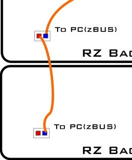
Connect the red end of a 30-cm single strand cable to the output of the first processor's interface (OUT).
-
Connect the other end (blue) of the 30-cm cable to the input on the interface port's second connector (IN).
- Repeat with 30-cm cables for each additional device with a PC-to-zBUS interface.
- Connect the red end of the second strand of the 5-meter cable to the output of the last processor's interface (OUT).
-
Connect the other end of this strand (blue) to the input on the WS interface (In).
These connections are sufficient to get your system powered on and tested. You can add other components, such as preamplifiers, video trackers, and data streamers, after you complete this guide. Connection information for these devices is in the corresponding section of the System 3 Manual, and devices that connect directly to the RZ are covered in Connecting Peripherals to the RZ.
Power On the Connected Components
Earlier you powered on the WS and set up your processor(s). Now you can power on the newly connected System 3 devices.
The power supplies for these devices are shipped from the factory configured for the desired voltage setting (110 V or 220 V). If you need to change the voltage setting, please contact TDT support at +1.386.462.9622 or email support@tdt.com.
UL compliance
The RZs and ZB1 Device Chassis are UL compliant. See the Operator's Manual booklet, or the corresponding section in the back of the System 3 Manual binder, for power and safety information.
-
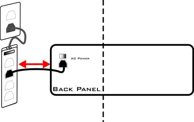
Plug the RZ or zBus device chassis power cable into a surge strip or battery backup connected to an AC power outlet. The power plug connector is located on the back panel of each device.
-
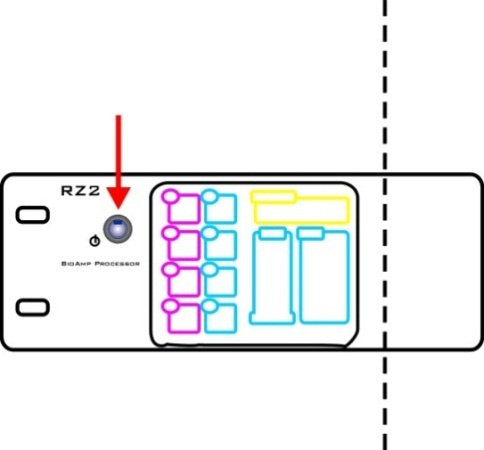
Switch on the power button for each device. The TDT System 3 devices can be powered on in any order. The RZ devices have a blue indicator light to show that the device is powered on.
The zBus chassis power switch has a green indicator light and will flash regularly (~1 Hz) until communication is initiated by TDT software, such as zBUSmon. After this initial communication, the green indicator light will glow steadily. The green indicator light also pulses when data is being transferred to or from the zBus chassis.
Next Steps
- Test Your System: confirm the PC can talk to your processors with zBUSmon.
- After Setting Up Your System: documentation, warranty, and where to get more help.