Legacy: the UZ2 USB 2.0 Interface
Older systems only
The UZ2 is the legacy USB 2.0 interface used with ZB1 chassis systems. New systems use either the Optibit interface (see Setting Up with a PCI Card or UZ3) or a USB 3.0 iConZ, see Setting Up an iCon over USB.
Install the drivers first
The TDT drivers must be installed before connecting the zBus chassis to your PC. See Install the TDT Drivers and choose the System 3 with legacy USB interface setup type.
When using the USB interface, a UZ2 interface module is required for every chassis which houses a programmable module such as the RX Multiprocessor modules or the PA5 Programmable Attenuator. The UZ2 is installed in the back bay of the chassis and should be connected to the PC USB port. If you have multiple chassis housing programmable modules you will need an available USB 2.0 port on the host PC for each UZ2 in a multi-chassis system. We typically recommend upgrading to an Optibit interface if a system requires more than three chassis.
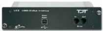
UZ1 and UB4
The UZ2 is designed for USB 2.0 ports. Some systems might use the UZ1 and UB4 interfaces designed for USB 1.1 ports. Connections for 2.0 and 1.1 compatible devices are similar; however, each system should use EITHER the UZ2 OR the UZ1/UB4 configuration. The two groups of devices should not be combined. If you are unsure how your system should be configured, contact TDT technical support staff for assistance. Also note that the UB4/UZ1 USB interfaces should not be used with the high-performance processors, such as RX5, RX6, RX7 and RX8.
Connect the Interface to the Host PC
To connect a device chassis (with UZ2 connector on the back of the chassis), use the supplied A-to-B type USB cable to connect the UZ2 chassis to the USB port on your computer.
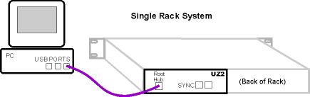
Using the UZ2 Sync
Each USB module has its own clock which will drift relative to each other. The Sync allows users to synchronize several modules that are mounted in different device chassis. The Sync line uses the clock from one USB module, the parent, to synchronize the clocks across all zBus device chassis.
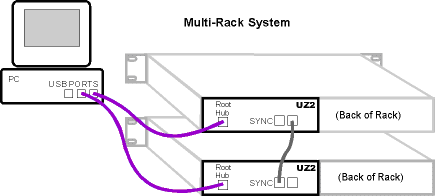
Connect the Sync Out of the parent clock to the Sync In of the child with a short patch cable.
To connect several device chassis, daisy-chain the connections between the child chassis. When the Sync lines are connected correctly the LED to the left of the Sync connectors should be lit on each child device. The LED on the parent will remain unlit. The LED should only flash when the Sync lines are not connected.
Start the zBus Hardware
After connecting the zBus chassis, plug the power cable(s) into a surge strip or battery back-up and turn on each chassis. When the chassis are turned on for the first time, the computer recognizes the TDT hardware as a new device and searches for and loads the USB driver for TDT System 3. An installing drivers message or Found New Hardware wizard may appear twice for each zBus chassis in your system. It is important that you allow Windows to install the driver both times.
Once powered, the green indicator light on the power switch of the zBus chassis will flash regularly (~1 Hz) until communication is initiated by TDT software such as zBUSmon or RPvdsEx. After this initial communication, the green light will glow steadily. You will also notice the power indicator light pulsing when data is being transferred to or from the zBus chassis.
Next Steps
- Test Your System: the UZ2-specific notes on zBUSmon.
- After Setting Up Your System: documentation, warranty, and where to get more help.