System 3 Installation Guide
Welcome! At TDT, we proudly provide the quality tools you need for your research. We take pride in using the most modern production methods and putting our products through a series of rigorous tests before they go out the door. The entire TDT team stands behind your new equipment and our support team has the experience and dedication to help you get the best from your equipment. Whenever you need us, we'll be ready to help. Contact us any time at support@tdt.com.
System 3 is a modular system controlled by a Windows-based computer. The PC handles:
- Configuring the hardware and software.
- Communicating with the TDT hardware and transferring data across a fiber optic interface.
- Displaying and working with data during and after acquisition.
Unpack Your Equipment
The images below show the most common elements found in a TDT system.
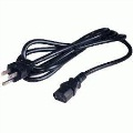
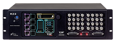
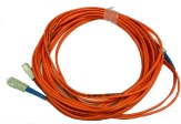
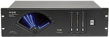
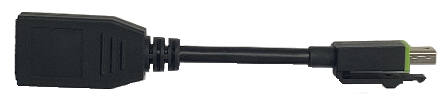
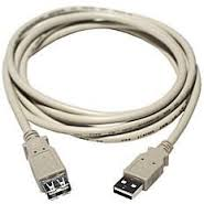
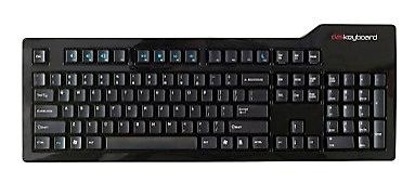
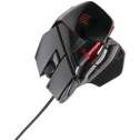
Not shown: monitors and other items such as stimulators, preamplifiers and headstages.
The most common elements found in a TDT system are:
- WS Computer Workstation with Keyboard and Mouse
- USB Extension and Video Cables
- Processor(s)
- Fiber optic cables
- Power cords
When setting up your system, we recommend starting with just the devices listed above. You can connect additional devices, such as amplifiers, headstages, and stimulators, after these devices are set up.
Identify Your Processors and Interface
The digital signal processor is the workhorse at the center of any TDT system. System 3 processors share a common operating system/language and come in several different form factors, each optimized for a particular type of research or set of tasks. These devices rely on communication with the computer, via a PC interface card or USB 3.0 port, for command and control. They may have a built-in interface (such as the RZ processors) or they may mount in a ZB1 chassis housing an interface module (for example RX processors).
Most other devices that connect to the system do so via the processor (such as the biological preamplifiers, video tracker, stimulators, and so forth). As a result, these devices do not need to be directly connected to the interface card or communications loop with the computer.
Less commonly, some other programmable devices, like the PA5 Attenuator, RA8GA amplifier, and HTI3 head tracker interface, must also be mounted in a ZB1 chassis with an interface. Non-programmable devices (such as speaker and microphone amplifiers, signal mixers, and so forth) may be mounted in a ZB1 chassis for power, but do not need to interface with the computer.
For now, you only need to identify your processors and other interface devices that must be directly in the communications interface loop with the PC or laptop.
RZ Processors
The RZ processor form factor uses an onboard Optibit interface that connects to either the PO5, PO5e, or PO5c installed in your computer. It may also use the UZ3, a version of the Optibit that can be used with a laptop via a USB 3.0 port. All three connect using a fiber optic cable.
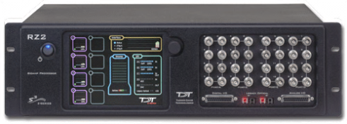
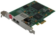
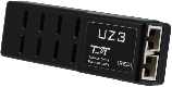
RZ processors (RZ2, RZ5D, RZ6, RZ10x) are the most commonly used processors for new systems and include an onboard PC interface.
ZB1 Device Chassis
The RX processors are typically shipped pre-installed in a ZB1PS zBus device chassis (shown below with no modules installed). The device chassis includes a bus system that distributes communication and power throughout the system. One or two modular devices can be mounted in the chassis' front bays, and an interface module must be mounted in the rear bay of any chassis housing a programmable device. This chassis may be used with both the Optibit and USB interfaces.

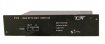
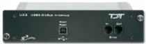
Non-RZ processors (RX8), rack-mounted amplifiers (RA8GA), and Attenuators (PA5) must be mounted in a ZB1 device chassis (rack) with a PC interface module (FO5) in the rear bay.
If your system includes more than one processor or attenuator, you must interconnect (daisy-chain) them during setup.
RM Processors
The RM form factor uses an onboard USB interface.
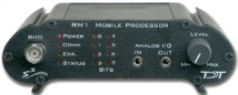 |
| RM1 (USB 1.0) |
Cables
All the accessory cables you will need to connect your system are included in the shipping box. These may include fiber optic, power and USB cables.
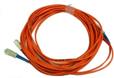

Other non-processor devices not shown might include a preamplifier, headstage, data streamer and more. These modules are shipped loose.
For more information about each device in your system, see the System 3 Manual.
Which Setup Do I Have?
The System 3 platform includes several options for interfacing with the PC, and which interface you use will determine how you set up your system. Find your system below and follow that page, then continue on to the shared steps.
Every setup that includes a programmable device also uses these shared steps: