Optical Connections
 |
|
Connection diagram for a 3-color fiber photometry setup. The RZ10x is configured with 6 LEDs, 3 Photosensors, and 1 Power Meter. The iX6 is configured with 3 LEDs, 2 Photosensors, and 1 Power Meter as a single row. |
A general connection scheme for a 3-color fiber photometry setup is shown in the above diagram. RZ10x deluxe models have six LED light driver outputs and four sensor inputs organized into two banks. The iX6 is essentially a single bank of an RZ10x with the power meter added in row. The connection scheme applies to a single row of the RZ10x or iX6.
The above RZ10x is configured with six Lux LEDs (405 nm, 465 nm, 560 nm), three Lux Photosensors, and one Lux Power Meter (typically installed in the Sen-D slot). For the 3-color setup, the Lux LEDs output light through a series of bandpass filters and dichroic mirrors ('fluorescent ports') called a Lux Optical Manifold (LxM6) that send excitation light to the subject and receive fluorescence back. The fluorescence signals are then sent to two Lux Photosensors (LxPS2 or LxPS1) on the RZ10x sensor inputs.
TDT supplies a Lux Cable Kit to make the connections to and from the RZ10x or iX6. The cables have color-coated necks to identify which Lux LED or Photosensor they attach to. The cable specs and important connection considerations are described in more detail below.
The RZ10x or iX6 can also be configured with M8 output connectors to drive external LEDs, or BNC inputs to receive external photosensor signals. These can be interchanged by the user.
Lux Pods
Important
Please turn off the RZ10x before adding or removing any connections (optical cables or electrical cables) to Lux Pods on the front banks.
LED_{x} - This is a Lux LED of a specified wavelength x. Common wavelengths used in fiber photometry include 405 nm, 415 nm, or 430 nm (autofluorescence detection, isosbestic control), 465 nm (GCaMP, dLight, GRAB sensors), 560 nm (TDtomato, mCherry, RCaMP). Please see the Lux LED webpage for a list of all available wavelengths.
M8 - This is an M8 connector that is commonly used for external LEDs. Standalone LEDs from Thor Labs and Doric both use M8 connectors for power.
PS1 or PS2 - This is the Lux photosensor.
PM1 - This is the Lux power meter.
BNC - This is a BNC (coaxial) connector that can be used to drive an external LED driver or receive the output of an external photoreceiver. This connector enables the 'DAC Out' or 'ADC In' checkbox, depending on if the BNC is for the Driver or Sensor hardware slots. Enable this checkbox only if you are using the BNC connector outside of the Fiber Photometry gizmo. It will be available on the 'DAC' and 'ADC' tabs of the RZ10x gizmo, respectively.
Fluorescent Ports - these are the series of filters and dichroic mirrors that send excitation light to the subject and receive fluorescence back. TDT makes four and six port optical filters called Lux Optical Manifolds that are preferred. Some labs might alternatively use a Doric Mini Cube
Fiber optic patch cords
TDT sells two different fiber optic patch cable kits with our recommended cables for two-color and three-color setups.
Two-Color Kit (LxFX-KIT-2C):
- (1) 400 µm core diameter cables for isosbestic LED to Lux Manifold connection
- (1) 200 µm core diameter cables for mid-range (typically Lx465) LED to Lux Manifold connection
- (1) 600 µm core diameter cable for the Lux Manifold to PS2 connection
- (1) 400 µm core diameter low-autofluorescent cable to serve as the Subject cable* when connected to the Lux PM1 power meter.
Three-Color Kit (LxFX-KIT-3C):
- (2) 400 µm core diameter cables for isosbestic LED and longer wavelength LED to Lux Manifold connection
- (1) 200 µm core diameter cables for mid-range (typically Lx465) LED to Lux Manifold connection
- (2) 600 µm core diameter cable for the Lux Manifold to PS2 connection
- (1) 400 µm core diameter low-autofluorescent cable to serve as the Subject cable* when connected to the Lux PM1 power meter.
All cables are 0.5 NA and are color-coded for the pod they connect to. They have a black jacket to prevent ambient light interference. TDT also recommends that customers order low auto-fluorescent specific subject cables from either Doric or Thorlabs.
Note
Fiber optic cables used in photometry have FC connectors, which have a 'notch-and-key' system. Make sure the key on the male FC connector is fully aligned with the notch on the female connector and that the cable is screwed all the way in. You will get a reduction in light power output if they are not aligned.
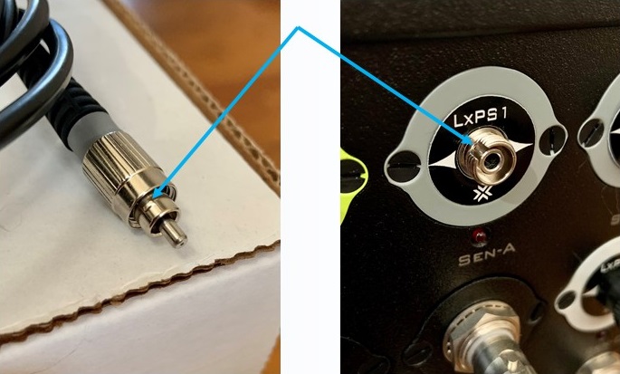 |
| Checking the FC Connection - Example of Notch and Key |
Note
* For accurate power measurements for your setup, the core diameter of the PM1 cable should match the core diameter of the Subject cable that you are using in your experiments (typically either 200 µm or 400 µm).
Using a 3rd Party Photosensor
This would be connected to a LUX BNC connector in place of the PS1 or PS2. For Newport photoreceivers, the gain should always be set to DC Low. This provides the widest bandwidth of light detection and detects signal clipping easier. Here is a link to the photoreceiver frequency response plots. If your photoreceiver has a 1x, 10x, 100x option, typically 10x will provide the clearest output response.