Preparing to Build a Signal
Prior to designing the constituent segments of a signal, you should define the parameters that will determine the entire signal, as well as any variables that might be used to change signal, segment, or component parameters as a function of the presentation interval, or SigGen Index (SGI).
Device Selection and Setup
When a new SigGenRZ file is created, the default device selection and setup are configured automatically, including:
-
Device selection
-
Stimulus playback circuit
-
Sample Period of the device
Device parameters are defined from the Setup RP Device dialog box, which can be accessed from the File menu.
To access the RP device dialog box:
- Click Target Device from the File menu.
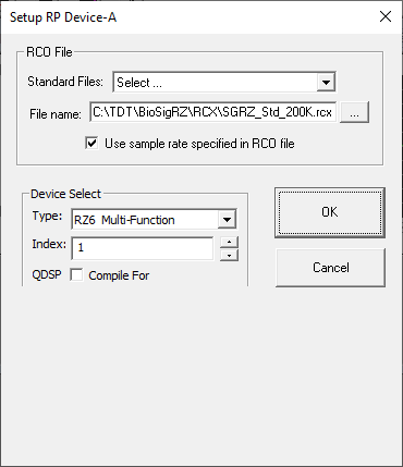
RCO File
Users can choose from the RCO files that come with SigGenRZ or make their own. Two Standard RCO files come with SigGenRZ:
-
SGRZ_Std_200K.rcx
-
SGRZ_Cal_200K.rcx
The first file is the standard stimulus play circuit. This circuit is compatible with both sweep play and continuous play configurations.
The second file is the standard calibration circuit. This circuit contains the necessary circuit components used for calibration in BioSigRZ.
Because SigGenRZ is targeted to the RZ6 processor, the maximum sample frequency for each RCO file is 200 kHz.
For more information about RCO files see the RPvdsEx Manual.
Device Select
Under Device Select, users may select the device type; however, SigGenRZ only supports the RZ6 Multi I/O processor.
Type: All System 3 devices are accessible from the dialog box. By default, the RZ6 Multi-Function processor is selected.
Index: This will typically be 1. A device index of zero means that the device type has not yet been selected. If the hardware set-up includes more than one RZ6 (highly unusual), the logical order of devices can be determined using the zBUSmon utility provided with the TDT Driver installation.
QDSP: Leave this option unchecked.
Bandwidth and Timing
The Bandwidth and Timing settings are only visible when the 'Use sample rate specified in RCO file' check box has been cleared. It is recommended that you use the sampling rate defined in the standard circuit files provided by SigGenRZ.
Signal Setup
Overall signal parameters include:
-
A name for the signal
-
The duration of the signal
-
The playback D/A channel
-
The signals attenuation
-
Calibration specifications
-
Variable definitions
Note
Signal parameters are defined from the Signal Parameters dialog box.
To access the Signal Parameters dialog box:
-
Click Signal from the Modify menu, or click on the Modify Signal button on the toolbar.
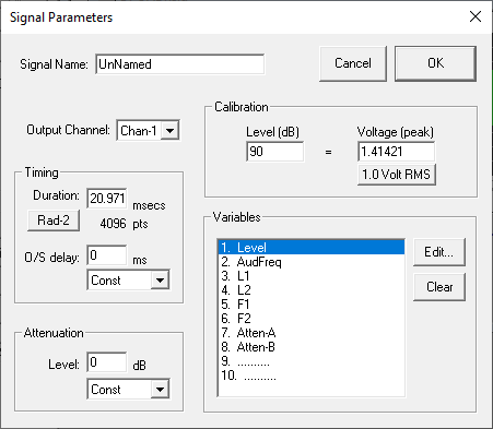
Signal Name
Signals may be named for user reference. Names may not exceed 15 characters in length.
Output Channel
SigGenRZ supports up to eight D/A channels for signal definition, and one channel for signal preview. Prior to signal preview, you must select the playback channel.
Output Channel: The RZ6 contains two D/A channels, select Chan-1 or Chan-2 for signal generation.
Timing
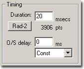
Duration
The Duration field of the Signal Parameters box defines the total duration of the signal in milliseconds. The value entered in this field determines the scaling of the Signal Window x-axis.
Radix-2
Sometimes a duration corresponding to a radix-2 number of sampling points is desired. For example, one scenario could be generating a waveform as short as possible while collecting enough points for Fast Fourier Transformation (FFT) analysis.
Click the Rad-2 button to truncates the value in the Duration field so that the total number of points in the signal is rounded to the closest radix-2 number. If you feel a different radix-2 number is what you want, you can double the duration value (or divide it by 2), and then click the Rad-2 button to get the next radix-2 number.
O/S Delay
The O/S Delay field specifies the onset delay of the signal in milliseconds. Onset delay is defined as the delay between the initiation of an SGI and the beginning of signal presentation.
Attenuation
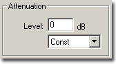
The attenuation field is used to specify the attenuation setting in the RZ6 processor. The drop-down menu allows you to control attenuation through the use of a user defined variable. See the RZ6 Multi I/O Processor in the System 3 Manual for more information on the RZ6 programmable attenuation.
When signals are presented to D/A devices, only 16-bit integer samples will be converted to analog signals. As a result, small amplitude signals will lose their details and appear distorted, and the signal to noise ratio will be reduced. To make good use of the dynamic range of the D/A devices, you should make your signal's amplitude as large as software and hardware allow, and use attenuators to adjust the signal level after D/A conversion to produce desired signal level.
Level
The level field specifies the level of programmable attenuation.
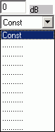
Constant or Variable Level
By default, Level is defined as Const, and therefore remains constant, regardless of the current SigGen Index value. Level may be varied as a function of the current SigGen Index value by assigning a predefined variable. See Variables, for more information.
To set Level to a constant or a predefined variable:
- Click Const or the desired variable name in the drop-down menu. If Level is a constant, enter the value in the Level textbox.
Calibration
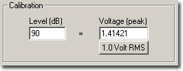
In designing signals in SigGenRZ, a decibel (dB) value is used to specify a level of a segment gain, or a component level. Since all signals will eventually be presented in terms of Volts, a dB-Volt relation or calibration must be specified. By default, all measurements of level in SigGenRZ are calculated in dB Volts with a reference of 1 Volt RMS. You may calibrate measurements of level by setting a specific Voltage equal to a designated dB level, or using one Volt RMS equal to the dB level.
Level
The Level field specifies a level in dB that equals the specified number of Volts (peak).
Voltage
The Voltage field specifies the number of Volts of the signal peak amplitude that equal the specified number of level units (dB). For example, in the specification (90 dB = 1 Volt (RMS)), a tone that is specified to be 90 dB will produce a tone with a 1-Volt RMS amplitude.
One Volt RMS
Clicking this button sets Voltage (peak) field equal to 1 Volt RMS (1.41421 (peak) Volts). This is convenient when you want to make your calibration in terms of RMS values.
Example: Calibrating units to reflect SPL
You may wish to calibrate SigGenRZ's level units so that they correspond to the sound pressure level (SPL) output of your system.
To calibrate SigGenRZ:
-
Generate a pure tone signal of a specified number of peak Volts.
-
Set Voltage equal to this number of peak Volts.
-
Measure the output of your system in SPL.
-
Set Level equal to the measured output in SPL.
Variables
SigGenRZ allows you to specify variables that may be used to change signal or segment parameters as a function of the presentation interval, or SigGen Index (SGI).
Up to ten variables can be defined in each signal. Variable values can be altered systematically, read in from a file, or specified by you prior to each presentation interval.
Variables may be created, edited, and cleared in the Signal Parameters dialog box or from the Variables Area of the main window.
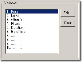 |
| The Variables Area of the Signal Parameters Dialog Box |
Edit
A new variable (except an alternating variable) can be defined at any available place of the Variables box.
To create a new variable:
-
Click on an available variable place (..........) in the Variables box.
-
Click the Edit button.
or
- Double-click on the available variable (..........) in the Variables box.
This will open the Signal Variables dialog box.
To edit an existing variable:
-
Click the desired variable in the Variables box.
-
Click the Edit button.
or
- Double-click the variable in the Variables box.
This will open the Signal Variables dialog box.
Clear
To delete an existing variable:
-
Click on the desired variable in the Variables box.
-
Click the Clear button.
Important
When a variable is deleted, SigGenRZ will remove its name from the Variables box, but will not always reset the parameters corresponding to this variable to their default values. Any parameter which uses this variable will still point to the place of this variable, and use zero as the variable value. Consequently, when a new variable is defined at this variable place, those parameters which use the deleted variable will automatically use the new variable instead. You should always remember that when you clear a variable, you must change all the signal/segment/component parameters which use the variable.
Variables Group Box
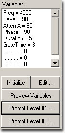
The Variables group box displays a list of all currently defined variables along with their current values corresponding to the current SGI value.
When more than one signal is used in an experiment, the SigGen Index of the channel-1 signal will be the active SGI in the application. As a result, when two signals are created and used in BioSigRZ, variables used in the signal assigned to the second channel should also be defined at the same variable locations in the first signal. For more information about creating variables, see Creating Variables.
Initialize
Clicking the Initialize button sets the SigGen Index (SGI) back to 1, causing any variables associated with the current signal to be initialized to their starting values. Clicking Initialize also causes any variable files to be read. When using a variable file, it is a good idea to initialize the variable(s) prior to assigning the variable(s) to parameters.
Edit
Clicking the Edit button will open the Signal Variables dialog box. Clicking any variable or empty variable position will select that variable or position. When the Edit button is clicked, the selected variable (or position) will be edited (or created) in the Signal Variable dialog box. Clicking Edit without selecting any variable or position will cause the first variable to be edited/created. Variables may be deleted in Signal Parameters dialog box.
To edit an existing variable:
-
Click the desired variable in the Variables box.
-
Click the Edit button.
This will open the Signal Variable dialog box and you can edit the parameters of this variable.
To create a new variable:
-
Click on one of the available variable positions (.......... = 0) in the Variables group box.
-
Click the Edit button.
This will open the Signal Variable dialog box. You can assign a name to this variable and select other parameters.
Preview Variables
Once you have defined the signal variables, it is possible to preview how they will change across intervals. Clicking the Preview Variables button opens the Variable Preview dialog box.
Prompt Level #1
You may wish to specify the value of a variable on the fly during the presentation of a stimulus signal. From the Signal Variable dialog box, you may create user-prompts. When you save your SigGenRZ signal file (see Working with the Complete Signal and Saving Signals, user-prompts will be saved as well and will be available when using the file in BioSigRZ.
When a user-prompt variable is defined, you can click the Prompt Level #1 or Prompt Level #2 button to access the Input Request dialog box and enter a new value for this variable. Current user-prompt variable value(s) will be used for all intervals of the signal preview.
To define Prompt Level #1:
-
Edit an existing variable or create a new variable and select the Prompted (Level 1) variable Method.
-
Click OK.
-
Click on the Prompt Level #1 button to open Input Request dialog box.
-
Enter the desired value in the Unknown Prompt field.
Note
The Prompt/Comment text box in the Signal Variable dialog allows you to specify your own prompt message for the Input Request dialog box.
From the Input Request dialog, you can view the prompt message and enter any test value you may wish to use for signal preview.
Prompt Level #2
In some cases, you may wish to vary parameters in a nested fashion. For example, you may wish to vary the frequency of a pure tone. For each frequency, you may in turn wish to vary the level.
You may specify a user prompt for a nested variable by using Prompt Level #2. In our example, this would be specified for level.
Note
Current versions of BioSigRZ does not support nested variables or Prompt Level #2.
To define Prompt Level #2:
-
Edit an existing variable or create a new variable and select the Prompted (Level 2) variable Method.
-
Click OK.
-
Click on the Prompt Level #1 button to open Input Request dialog box.
-
Enter the desired value in the Unknown Prompt field.
If you have multiple Prompt Level #1 or Prompt Level #2 variables defined, the Input Request dialog box will appear repeatedly until enough values are entered for all Prompt Level #1 or Prompt Level #2 variables.
Creating Variables
You may change the value of signal and segment parameters as a function of the SigGen Index (SGI) value by defining variables. From the Signal Variable dialog box you can define the names of up to ten variables, as well as specify starting values, minimum values, maximum values, and the manner in which the value will be varied.
You may access the Signal Variable dialog box from the following:
-
The Variables area of the main SigGenRZ window.
-
The Variables group box of the Signal Parameters dialog box.
To access the Signal Variable dialog box:
Do one of the following:
- Click a variable in the Variables box to edit an existing variable.
or
-
Click an available variable place (..........) in the Variables box to create a new variable.
-
Click the Edit button.
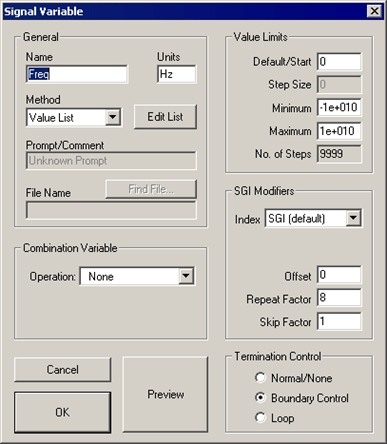
General Variable Parameters
General variable parameters include:
-
Name
-
Units
-
Method
Name
Variables are defined using names that may not exceed 12 characters in length. You can enter a variable name by typing in the Name field. When you change a variable name or its parameters, SigGenRZ will also make changes to those parameters using this variable when editing variable is completed. Using a name reflecting the physical nature of the variable is highly recommended.
Units
In the Units field, you may enter up to 5 characters to describe the variable's intended unit of measure. The unit value you entered here is only a reminder, not a standard for data conversion.
Three basic units used in SigGenRZ are: decibel (dB) for level, millisecond (ms) for duration, and Hertz (Hz) for frequency. You should use a correct unit for this field.
Note
The actual unit of measure assigned to the variable will be determined by the SigGenRZ parameter with which the variable is associated. For example, you may have defined a variable named "Freq" and described its Units as "Hz." However, if you assign "Freq" to a duration parameter, its unit will be milliseconds.
Method
Method defines the mechanism (function) of altering variable values as a function of the SigGen Index (SGI). There are 14 methods available in SigGenRZ.
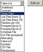
Variable methods include:
-
Undefined: no Method has been defined for the current signal variable. The variable will be zero for all the signal intervals.
-
Constant: this method is most useful when more than one SigGenRZ parameter will be set to the same value. Constant defines a variable that will always have the same value as given in the Default/Start field of the Value Limits box. This value will be a floating-point constant between 1.2E-38 to 3.4E+38.
-
Linear Step: For each SigGen Index (SGI) increment, Linear Step defines a variable that will increment by the Step value specified in the Value Limits box.
-
Log Step (base 2): defines a variable that will perform as a base 2 exponential function of SGI:
Variable = Start * 2 ^ (Step x (SGI-1))
The Start and Step values are defined in the Value Limits group box of the Signal Variable dialog box.
-
Log Step (base 10): Log Step (base 10) defines a variable that will perform as a base 10 exponential function of SGI:
Variable = Start * 10 ^ (Step x (SGI-1))
The Start and Step values are defined in the Value Limits group box of the Signal Variable dialog box.
-
Random per SGI: The value used for the variable is a random number between the Minimum and Maximum set in the Value Limits group box. The random numbers are generated with a uniform distribution within an SGI.
A Step Size of zero will give a full floating-point random value within the specified range. Use a non-zero to define the resolution of the result (e.g.: a Step Size of 0.1 might produce values of 3.7, 2.9, 7.2, etc.).
-
Prompted (level 1): To specify the value of a variable on the fly during the presentation of a stimulus signal, you may create user prompts. These prompts will be available in BioSigRZ.
If you have defined a level 1 prompt for the selected variable, the Prompt Level 1 button will be enabled, and you can use this button to enter variable values when you preview the signal.
-
Prompted (level 2): Using this method, you can be prompted for a value at run-time. Level 2 prompts are used for 2nd level nested variables.
-
Schedule File: Variable values are read from a schedule file. The file name is specified in SigGenRZ and is used by BioSigRZ.
Each variable in a variable file can have up to 100 values.
-
Sch File (prompted): Variable values are read from a schedule file. The file name is specified by you during run-time. One usage of this method is to allow user to use more user-defined variable values. For example, when you want to use more than 100 specific variable values, you can put them into more than one variable file, and access them one after another.
File prompt will be available in BioSigRZ. While previewing signals in SigGenRZ, you can display this prompt and assign schedule file(s) by clicking Prompt Level #1 button in SigGenRZ Signal Window.
-
Alternating: The value of the variable alternates between the values defined in the Minimum and Maximum fields. The variable value does not depend on SGI value, but on the number of the continuous presentation of the current signal interval. In the Variables group box, an alternating variable must be defined next to another predefined variable, or as the first variable. See the BioSigRZ Manual for more information.
Note
Due to the nature of this variable, this feature is not available during Play or Play All in SigGenRZ since the "continuous presentation of the current signal interval" condition is not met. However, you can test the alternating effect by repeatedly initializing variables. Alternating variables function when the SigGenRZ signal is used as a stimulus in TDT's BioSigRZ application.
-
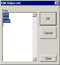
Value list: Variable values are specified in SigGenRZ by you during the signal design process. A maximum of 100 variable values can be specified for the variable.
To enter or modify a value list:
-
Choose Value List from the Method box.
-
Click the Edit List button.
-
Enter values to define the variable.
-
-
Dynamic: Dynamic variable values are controlled by the run-time application, usually based on a subject feedback. See the BioSigRZ Manual for more information.
-
CSV File: The values for this variable type are reads from windows standard Comma Separated Value (CSV) files which allows for matrix (two dimensional) arrays where each row is an SGI and each column is a repeat. The CSV files used by this variable type are easily generated and saved using EXCEL or similar programs. A typical CSV file is shown below:
1, 6,11,16,21,26
2, 7,12,17,22,27
3, 8,13,18,23,28
4, 9,14,19,24,29
5,10,15,20,25,30
6,11,16,21,26,31
7,12,17,22,27,32
8,13,18,23,28,33
9,14,19,24,29,34
A variable using this CSV file would use the current SGI to index down to a specific row. For example, for SGI = 6 the row with numbers 6,11,16,21... would be indexed. If this variable was used in the component of a repeating segment, the first repeat would use the value 6 and the second would use 11 and third 16 etc. This allows the user to get full control of how repeats are computed and where they are applied to the overall waveform.
-
Randomize: The value used for the variable is a random number between the Minimum and Maximum set in the Value Limits group box. The random numbers are generated with a uniform distribution.
A Step Size of zero will give a full floating-point random value within the specified range. Use a non-zero to define the resolution of the result (e.g.: a Step Size of 0.1 might produce values of 3.7, 2.9, 7.2, etc.).
Prompt/Comment
If the defined method is Prompt, you will be defining the variable values. If the defined method is Sch File (prompted), you will be defining the name of the schedule files. In these cases, a user prompt will be necessary, and the text string(s) entered in the Prompt/Comment field will be used as the Prompt. A prompt may be up to 50 characters in length including spaces.
To define a Prompt/Comment:
-
Edit an existing variable or create a new variable and select Prompted (level 1 or level 2) or Sch File (prompted) from the Method dialog box.
-
Type in the desired text in the Prompt/Comment field.
File Name
If the chosen method is Schedule File, a schedule file must be specified. Schedule files are defined as an ASCII file with the file extension *.sch.
To define a schedule file:
- Type in the file path and name
or
-
Click the Find File button.
-
Choose the file name.
When you choose Sch File (Prompted), you do not need to enter a file name at design time; however, you may need to supply the file when you run an application. Specifying a schedule file for a Sch File (Prompted) variable is not required when you preview a signal in SigGenRZ.
Combination Variables
In many cases, a simple variable is not sufficient to define a signal. For example, consider a signal consisting of two segments in which the first segment has a variable duration, and the second segment starts 10 milliseconds after the first segment. You could calculate the start times of the second segment by hand, or you could define a combination variable.
A combination variable is a variable whose value is calculated by performing a mathematical operation on another variable or a constant.
To Define a Combination Variable:
-
Open the Signal Variable dialog, either by choosing Signal under the Modify menu and then clicking the Edit button, or by clicking the Edit button on the side bar.
-
Name and define the combination variable in the General box.
-
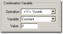
In the Combination Variable box select an Operation to apply to this variable (V in the Operation formula). Combination variables can be defined using addition, subtraction, multiplication, and division.
Operation:
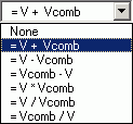
The Variable drop down menu in the Combination Variable box is used to define
Vcomb in the operation. Vcomb can be defined as either a constant, and its
value entered in the Value box, or it can be defined as another variable.
Combination Variable Example
This example illustrates how to use a combination variable to build a signal consisting of two segments in which the first segment has a variable duration, and the second segment starts 10 milliseconds after the first segment.
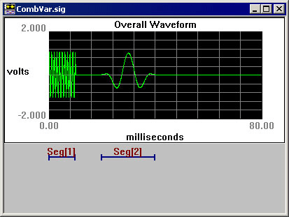
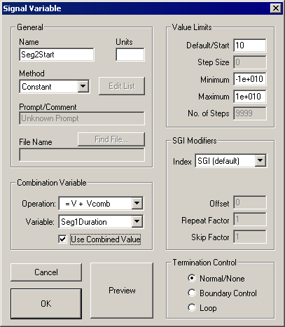
Seg1Duration is a simple variable that specifies the duration of the first segment. A combination variable, Seg2start, is defined so that segment 2 starts 10 msec after segment 1. Seg2start is defined with method Constant and Default=10.
In the Combination Variable box Vcomb is set equal to the variable Seg1Duration. V+Vcomb is selected so that Seg2start = 10 msec + Seg1Duration.
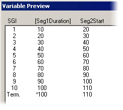
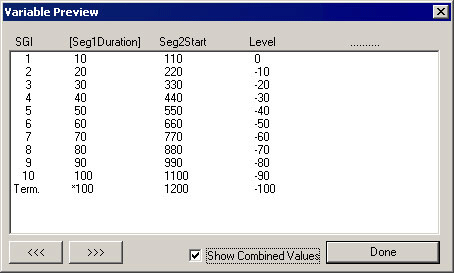
We can preview the results of the combination variable operation by selecting Preview. The uncombined value of the combination variable Seg2start is displayed. To see the results of the combination operation, check the Show Combined Values box. In this case you can see that Seg2start begins 10 ms after Seg1Duration.
Previewing Variable Values
You may wish to preview the manner in which parameter values will vary as a function of the SGI. Variable values may be previewed from the Variable Preview dialog box.
To open the Variable Preview dialog box:
- Click the Preview button.
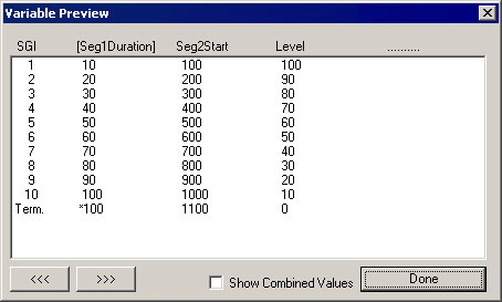
The Variable Preview dialog box displays the current stimulus schedule. Variable values are shown for each SGI.
Scrolling
The Variable Preview dialog box can display up to five variables. You may view additional variables by scrolling to the right or the left.
To scroll to the right, click on the ![]() button.
button.
To scroll to the left, click on the ![]() button.
button.
To scroll up and down, use the vertical scroll bar.
Showing Combined Values
You may have defined a combination variable. By enabling Show Combined Values, you may display the values of this combination variable as a function of the SGI. When Show Combined Values is not enabled, only their primary values will be displayed for combination variables.
To enable Show Combination Values:
- Check the Show Combination Values box.
Enabling this feature would cause the previous stimulus schedule to appear as follows:
Value Limits
From the Value Limits group box you can define the manner in which a variable value changes as a function of the SigGen Index (SGI) value. You can also define the range of allowable values for the variable. For combination variables, these values will only apply to primary variable(s), and will not limit the combination variable result. However, a zero will be used when the combination variable result becomes a divide-by-zero.
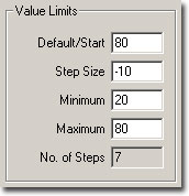
Default/Start
Default/Start defines the value of the variable when the SigGen Index = 1. This is also the value for a constant variable. When prompt variables (Prompt Level 1, Prompt Level 2, and Prompted File) and Dynamic variables are defined, this value is also the default variable value before the value is specified.
Step Size
Step Size must be defined when using the following functions:
-
Linear step
-
Log Step (base 2)
-
Log Step (base 10)
-
Randomize
-
Random per SGI
Step determines how much the variable will be systematically varied as a function of the SigGen Index value. Default Step Size for a Randomized variable is 0, which causes SigGenRZ to use the full floating point precision to generate the variable values. A zero Step Size for other functions will define a constant variable.
Minimum
In the Minimum field, you define the minimum allowable value for the variable.
Maximum
In the Maximum field, you define the maximum value allowed for the variable.
Note
Minimum value must be smaller than Maximum, and Default/Start must be within Minimum and Maximum range.
No. of Steps
This field displays the total number of steps between the minimum and maximum variable values, when appropriate. This field is not editable.
SGI Modifiers
SigGen Index (SGI) is a unique number which starts at 1 and increments by 1 when an interval is presented. This SGI applies to every variable by means of SGI Modifiers. These SGI Modifiers become important when SigGenRZ is used to design signals with complicated variables or nested variables.
By default, a stimulus presentation begins with the SGI = 1. Often, the stimulus signal generated at SGI = 1 is presented until a desired number of response signals have been attained. The SGI is incremented by 1 then all variables and the entire signal are updated. This process continues until all SGIs have been presented. Through use of SGI Modifiers, it is possible to customize the process of incrementing the SGI for individual variables.
You may:
-
Start variable calculation with an offset to SGI.
-
Repeat SGI.
-
Skip a specified number of SGIs.
-
Create nested variables
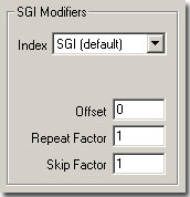
Index
By default, variables are indexed using the SigGen Index or SGI. SGI indexing can also be replaced by another variable with an optional scalar applied. This is useful for a multitude of applications when one or more variables should be calculated based on a single control variable.
Offset
The initial SGI is always 1. When SGI is used to calculate variables, any deviations from this default value are termed offsets. If you wish to start stimulus presentation with a variable calculated based on a modified SGI = n, then enter n in the Offset field. If the variable's values are 0, 1, 2, 3, 4, 5, ..., corresponding to SGI = 0, 1, 2, 3, 4, 5, ..., an Offset = 2 will result in modified SGI = 2, 3, 4, 5, 6, ..., and so the variable's values 2, 3, 4, 5, 6, ..., correspond to SGI = 0, 1, 2, 3, 4, 5, ....
The default value of Offset is 0, that is, the modified SGI equals to SGI. The value of Offset must be no less than 10,000 and no greater than 10,000.
Repeat Factor
The Repeat Factor field specifies the number of times, r, an SGI will be used as modified SGI. For example, when r = 2, modified SGI will be 1, 1, 2, 2, 3, 3, ..., corresponding to SGI = 1, 2, 3, 4, 5, 6, ....
By default, Repeat Factor is set to 1 (use SGI once). Repeat Factor may be no less than 1 and no greater than 100.
By using a Repeat Factor in tandem with a Termination Control specification of Loop (see next section), you can create nested variables.
Skip Factor
The Skip Factor field specifies the number of the SGIs is to be ignored in the modified SGI. For example, if Skip Factor is 2, modified SGI will be 1, 3, 5, 7, 9, ..., corresponding to SGI= 1, 2, 3, 4, 5, 6, ....
By default, Skip Factor is set to 1. Skip factor may be no less than 1 and no greater than 100.
Termination Control
You can control the termination of SGI, and thus the signal play by choosing one of three types of termination control.
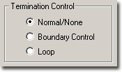
Normal/None
When Normal/None is selected, the variable will not be considered in termination control. Thus, if a minimum or maximum variable value is reached, signal play will not terminate, nor will the variable value loop. Continuous signal generation will be based on the final variable value. In this case, signal play will be terminated by other variables or manually.
Boundary Control
Boundary Control provides a method of experiment termination. When Boundary Control is chosen, the SigGen Index (SGI) will not be incremented and signal play will halt if such an action would cause the value of the variable to be:
-
Less than the Minimum value.
-
Greater than the Maximum value.
Such failure to increment the SGI produces differing results, depending on the application.
Boundary Control in SigGenRZ:
In SigGenRZ, when a boundary is reached and the SGI is no longer incremented, all signal generation halts.
Boundary Control in BioSigRZ:
When a boundary is reached and the SGI ceases to be incremented, signal generation will continue for the current SGI, but no more response data will be collected.
Note
Specification of Minimum and Maximum does not provide boundary control. Minimum and Maximum simply define the limits of parameter variation. The variable will not be allowed to go beyond either of these limits. With Boundary Control disabled, SigGenRZ will continue to increment the SigGen Index and produce a signal during preview of multiple intervals, even if a Minimum or Maximum parameter value has been reached.
Loop
When Loop is chosen, parameters continuously loop through the series of variable values as SGI increments.
Using Schedule Files
When other functions cannot generate desired variable values, you may design custom variables using Schedule Files. By default, SigGenRZ looks for files with the .sch file extension.
What Is a Schedule File?
A schedule file is an ASCII text file that defines one or more user-customized variables by specifying the following:
- Variable Name: The variables in SigGenRZ must match the variables defined in the schedule file.
- Number of Repetitions for each variable: Set this number equal to the number of times you want the signal repeated for a given variable value.
- A list of variable values for each variable: Up to 100 values may be specified for each variable in the schedule file.
Creating a Schedule File
Schedule Files may be created with any editor that saves ASCII text files such as notepad.
Schedule File Structure
Text Strings: Most users will want to include some text information in their Schedule File that describes the variable(s) defined. Such information can be placed at the top of the file, or between Variable Definition blocks.
Variable Definition: One or more variables may be defined in a Schedule File. Each variable is defined in a variable block. The beginning and end of a variable definition block are marked by a pair of brackets ({}). The variable definition block structure is defined on the following page.
{
Variable Name
Number of signal repetitions, r
Variable value 1
Variable value 2
....
Variable value n
}
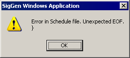
Important
The additional empty line under the closing bracket is necessary. Failure to provide this line will result in an Unexpected EOF (End Of File) error.
Sample schedule file
Here is a sample schedule file.
This controls Delta_T, the separation between masker and probe.
{
Delta_T
4
82.0
66.0
58.0
54.0
52.0
51.0
50.0
}
This is a list for intensity of the masker. We'll run each intensity level for all values of Delta_T.
{
Masker_Level
1
20.0
30.0
40.0
50.0
}
Nesting Variables
In some cases, you may wish to vary parameters in a nested fashion. For example, you may wish to vary the separation between a masker and its probe through the use of a variable such as Delta_T. For each Delta_T, you may in turn wish to vary the masker level.
The variable file shown above is an example of a two-level variable nesting. Please note the following:
-
Variables are defined in the order of nesting.
In this case, the separation between a masker and its probe, Delta_T, will be varied. For each value of Delta_T, the intensity of the masker, Masker_Level, will be varied. Thus, Delta_T is defined first; Masker_Level is defined second.
-
The Number of Repetitions parameter is used to control repetitions during nesting.
There are four values for Masker_Level. This means that for each value of Delta_T, Masker_Level level will be varied four times. This is indicated by setting the Number of Repetitions for Delta_T to four.
For each Masker_Level, the signal will be played only once. This is indicated by setting the Number of Repetitions for Masker_Level to one.
-
Nesting variables can be defined in SigGenRZ without using a schedule file.
In the above cases, we can define Masker_Level with proper limits and Loop boundary control so it will loop over 4 values, and define Delta_T with a Repeat Factor of 4, we can obtain the same nested result.
-
Using a schedule file you can define more complicated nesting variables.
You can only achieve a two-level nesting if you do not use a schedule file.
Using Variables Defined in a Schedule File
To access variables in a Schedule File:
-
Type the variable name in the Name field.
-
Click the Find File button.
-
Select the desired file.
or
- Type in the desired schedule file path and file name.
Note
SigGenRZ uses variable names to access variable values in schedule files. The variable name typed in the Name field must match exactly the variable name assigned in the schedule file.
Initializing Variables in a Schedule File
When a variable is created using a schedule file, variable values will be read as soon as the variable is accepted (clicking the OK button). However, when a file variable is edited (assigned with another schedule file), or the schedule file is altered, variable values may not be read automatically. At this time, when the current signal interval is previewed using Play button, the presented signal may not be the one with new variable values.
In many cases, the value of a file variable is read at the time it is assigned to a parameter. This value will be a function of the current SigGen Index (SGI). In some cases, however, the variable value is not automatically read upon assigning the variable to a parameter. This can cause problems if the parameter must fall within a specific range. It is a good idea to manually initialize all file variables prior to assigning them to parameters.
To manually initialize a file variable:
- Click the Initialize button of the SigGenRZ main window.
Using Variables to Control System 3 Parameter Tags
When the demands of the required stimulus are beyond SigGenRZ's basic signal design abilities, SigGenRZ can be used to control device properties through parameter tags. Parameter tags are a powerful component of the RCO file and can be used to control various aspects of a stimulus such as programmable digital filtering, waveform generation, and even hardware.
A good working knowledge of System 3 hardware and RPvdsEx is needed before modifying the SigGenRZ RCO files.
System 3 Hardware and Software
The RZ6 multi I/O processor is an easy-to-use, easy-to-program data acquisition and stimulus presentation device. Each RZ6 contains analog outputs and inputs, digital inputs and outputs and a development program, RPvdsEx. Compiled RPvdsEx files program the signal processor for stimulus generation and data acquisition using a drag-and-drop design environment. Circuits generated in RPvdsEx can be saved for use with other TDT software applications. For more information about creating RCO files, see the RPvdsEx Manual.