Components of Segments
Components are the foundation of a SigGenRZ signal. Each component is a basic waveform of the signal. It is through the definition of component parameters that the time-varying waveform is defined.
How to Build a Segment - Signal Components
Components are the building blocks of a segment. The manner in which a component is generated is determined by the Generation Method assigned to the segment it is building.
Components may be generated in the following ways:
-
Generation Method
-
Time
-
Frequency
For example, you are building a segment, seg1, composed of two component pure tones. You have chosen a Time as the Generation Method. Both of its components will be defined in the time domain.
How Components are Generated
SigGenRZ generates a time-domain waveform for every component, regardless of which Generation Method, Time or Frequency, has been selected.
Time: When time-domain parameters are specified, SigGenRZ uses these parameters to generate a time-domain waveform. Specifically, SigGenRZ utilizes built-in functions to calculate signal points when time method is used.
Frequency: When frequency-domain parameters are specified, SigGenRZ computes the magnitude spectrum of the signal based on those parameters, generates a phase spectrum, and then converts them into a complex buffer pair (real and imaginary buffer pair). An inverse Fast Fourier Transform (iFFT) will then be applied to the complex buffer pair to generate the time-domain waveform.
Combining Components
The time-domain component waveforms generated by SigGenRZ are always combined additively.
Note
The RZ6 D/A converters limit the Voltage range to ±10 V. Clipping will result during signal play if Voltages exceed this range. Combining components that are in phase may result in segment Voltages in excess of ±10 V.
Designing Signal Components
Components may be designed from the Component Parameters dialog box. Component Parameter dialog box can be accessed from Edit Segment Parameter dialog box, Component group.
Components
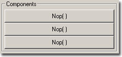
To open the Component Parameters dialog box:
- Click the desired Component button.
Component buttons read Nop[ ] (no operation) before a component has been added. After a component has been added, summary information is displayed on the button.
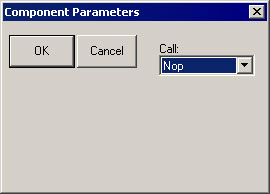
Component Parameters Dialog Box
Components of a signal segment are defined in the Component Parameters Dialog Box. Under Call there is a pull-down combo list box which contains all possible signal components SigGenRZ can generate. Clicking on the Drop-down box will display the list. There are different options for Time and Frequency methods.
Call
The Call list box displays a list of options you may use in designing your segment. From this list you may choose the type of signal component you wish to define. Depending on which Generation Method you have chosen (Time or Frequency) you will see one of two lists of options:


Parameter Definition Fields
Once you have chosen the desired type of signal component, corresponding Parameter Definition Fields will be displayed in the dialog box. Each field specifies a parameter required for definition of the component. You must understand and fill the parameter values correctly for SigGenRZ to generate the desired signal.
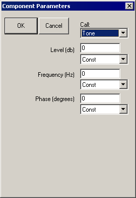
Each Parameter Definition field is associated with:
-
A Value field for entering a constant value
-
A Variable box containing the names of all defined variables
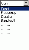
To specify a constant value:
-
Choose Const from the Variables box (this selection is default).
-
Enter the desired value for the constant in the Value field.
To specify a variable value:
- Choose the desired variable from the Variables box.
Note
In most cases, component definition requires the specification of a component level. When using the Application Methods, Add or Multiply, level is defined in terms of the system calibration specified during signal parameter definition. When using the modulating Applications Methods Multiply, Divide, Gap, Inv Gap, component levels of this segment are NOT defined in terms of the system calibration specified during signal parameter definition, but is instead defined as 0 dB equal to 1 Volt. For example, specification of a tone with a level of 0 dB will create a tone with a peak amplitude of 1 Volt.
The Time Options
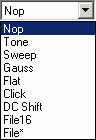
Nop: Causes no operation to be performed, so no component will be defined. Choosing Nop for an existing component causes the component to be removed from the segment.
Tone: Produces a pure tone waveform in the time domain. Parameters include:
-
Level in dB
-
Frequency in Hz
-
Phase (cosine) in degrees
Note
The phase of the Tone component is considered as cosine degrees, that is, a tone with a zero degree phase will begin generating the waveform at the peak of a tone waveform, which is 90 degrees out of phase from a sine waveform.
Sweep: Produces a frequency sweep (a tone with its frequency varying continuously). Parameters include:
-
Level in dB
-
Sweep rate in Hz/s
-
Starting frequency in Hz
-
Phase (cosine) in degrees
Sweep rate can be either positive or negative. When sweep rate is positive, the generated signal will have an increasing frequency, or when it is negative, a decreasing frequency. A pure tone will result if the sweep rate is specified to be zero.
Gauss: Produces random noise with a Gaussian distribution. Parameters include:
- Level in dB
Note
The Gaussian distribution has a zero arithmetic mean, and in SigGenRZ its standard deviation is the level specified above. If you generate a Gaussian noise with a specified level, the actual noise peak amplitude will be higher than the specified level.
Flat: Produces random noise with a flat (uniform) distribution. Parameters include:
- Level in dB
Note
The waveform sample points of a flat noise are uniformly distributed between zero and the level specified above.
Click: Produces a two-level (bi-polar) click. There are two peaks (positive and negative) in the bi-level click. Parameters include:
-
Level one in dB
-
Level two in dB
-
Duration one in ms
-
Duration two in ms
-
Polarity (Enter +1 or -1, other values will affect the signal level.)
Two-level click can be considered as a pair of two opposite polarity clicks. Level one and Duration one specify the level and duration of the first click, and level two and Duration two, the second. When Polarity is a positive number, the first click will be a positive one, the second the negative one, and when Polarity is negative, the first will be negative, and the second positive. A zero Polarity will result in a Nop. The absolute Polarity value will also be used as a scaling factor to be multiplied to the generated component.
For example, a Polarity value of 1.5 will result in a positive-negative click pair, and their peaks are 1.5 times of their levels.
If you want to generate a single-level click, you can specify a zero duration to either first or the second click. Durations must be either positive or zero. A negative duration will be taken as zero.
DC Shift: Produces a DC offset (from 0 Volt). Parameters include:
- Level in dB
Since the Level of DC Shift operation is a dB value, only positive DC shift can be achieved with one DC shift component. To make a negative DC shift, you can generate a positive one first in one segment with desired level, and make another one in a new segment with twice the desired level and subtract it from the signal.
File16: This option allows you to define a component based on one or a group of headerless, 16-bit integer binary files. The file extension must be .000. When you use only one file, the real file extension must be 000. When you use a group of files, the file extensions must be three-digit numbers (for example, five possible file names: file.005, file.004, file.003, file.002, file.001, and only file.000 should be entered in the parameter field). Parameters include:
-
File name (always filename.000)
-
File extension variable. If there is only one file, Const should be selected. If more than one file will be used, a variable must be selected, and the variable values must be the three-digit numbers of the file extensions.
When a File16 file is read to SigGenRZ in time domain, the data points will be converted into Voltage values based on 16-bit integer range of values (-32768 to 32767) and the RZ6 D/A hardware range of output levels (±10 V).
File*: Allows you to define a component based on one or a group of sound files. The file extension must be .000. Refer to File16 for using more than one file. In addition to reading raw 16 bit integer and floating point data files, FILE* supports a number of file formats including the sound file format used on PCs, WAV files. In addition, FILE* includes arguments for controlling file seek position and the number of words read from the file, allowing FILE* to excerpt specified portions from files under variable control.
Finally, FILE* supports a versatile file-name access convention whereby the accessed file name is built using any combination of user defined text and a variable value. FILE*'s most powerful feature may be the indirect-file-access control whereby the named file contains a list of files names that are indexed using a specified variable to select the actual data file name. Parameters include:
-
File Type
-
File Type variable
-
Seek Position
-
Seek Position variable
-
Excerpt Size
-
Excerpt Size variable
-
Indirect File Offset
-
Indirect File Offset variable
-
File name (always filename.000)
-
File extension variable. If there is only one file, Const should be selected. If more than one file will be used, a variable must be selected, and the variable values must be the three-digit numbers of the file extensions.
File Types
By default, FILE* will load raw floating-point data without offset. When FILE* is selected, the first argument becomes the File Type to be accessed. This parameter can be specified with a variable, but care should be taken that the variable generates legal values that match the actual file type. It is possible to 'hang' the program by mismatching the file type specified with the actual file being accessed. The currently supported file types are:
-
Raw Float index = 0
-
Raw Int16 index = 1
-
ASCII index = 2
-
WAV (Mix) index = 3
-
WAV (Left) index = 4
-
WAV (Right) index = 5
Raw Float: Data samples are organized in a sequential floating point format using standard IEEE 32-bit (four byte) data. Numbers should be scaled between ±10.0 corresponding to the ±10 Volt peak to peak output of the RZ6 D/A converters.
Raw Int16: Data organized as a raw file of 16 bit integers stored in MSB first format. This component call is compatible with the INT16 file format supported by SigGenRZ and includes the other features of FILE* like indexing etc. Data should be scaled between +32767 and -32768 which will be converted to ±10 Volts when loaded.
ASCII: This is a standard text list of floating point numbers. These lists can be generated with EXCEL or MATLAB. Data should be scaled between ±10.0 as with Raw Float. It should be noted ASCII data files may be quite large with a single data value taking over 20 bytes of disk space.
WAV Files: SigGenRZ supports the Windows WAV file format. While WAV files can be either 8- or 16-bit, SigGenRZ only supports 16-bit files and will fail to load if an 8-bit file is selected. A number of free-ware Windows programs are available for editing and formatting WAV files. These programs typically allow the user to get the file into the proper 16 bit format with the needed sample rate.
Important
The FILE* loader will NOT convert the sampling rate of the loaded file to match that specified within SigGenRZ. It is the user's responsibility to ensure the WAV files being used have the appropriate sample rate.
WAV (mix), WAV (left) and WAV (right): Mono and Stereo WAV files can be read. When mono files are used, any of the WAV component calls will load the same data. If stereo files are used, use the mix, left and right options to load the needed channel. WAV (mix) sums the left and right data and scales down by 6 dB.
Seek Position
Seek position and excerpt sizes are used to select the portion of the sound file you wish to load. The SEEK_POS parameter can range from 0 to files_size - points-to-read. Seeking beyond the end of the file will cause garbage to load. It is the user's responsibility to limit file access to the files size. The SEEK_POS parameter is useful for accessing random segments from a pre-computed noise file. Often masking noise is needed with specific frequency characteristics. A large noise file can be pre-computed and saved to disk. The SEEK_POS argument can then be fed with a RANDOMIZED variable accessing random noise segments generating a pseudo-random noise effect.
Excerpt Size
The EXCERPT SIZE parameter is used to select the number of points to be read from the file. Normally (EXCERPT SIZE = 0) FILE* will read enough points to fill the target segment. That is a 100 ms segment sampled at 50 kHz will load 5000 points. The EXCERPT SIZE parameter can be used to override this behavior, by limiting the number of points read to something less than the 5000 needed to fill the segment. This argument is very useful for reading sound segments from raw data files with variable lengths. Also if one wishes to take excerpts from a larger file, this parameter is useful for controlling the number of points read into the segment.
File Name
FILE* supports a versatile file naming/lookup scheme, allowing the output of a variable to be inserted at any point within a text field specifying the file name. The examples below illustrate how the file name parameter functions.
Simple fixed file access.
File Name = "sound.wav"
SG Variable = Const
File Accessed = 'sound.wav'
* Wildcard file access Example 1: Will access file with the name built using the text specified and the current value of the variable named QSPEC.
File Name = "snd***.wav"
SG Variable = QSPEC = 247.0
File Accessed = 'snd247.wav'
* Wildcard file access Example 2: Builds file name as specified and truncates the number to the integer portion.
File Name = "sound.g**"
SG Variable = QSPEC = 12.8
File Accessed = 'sound.g12'
* Wildcard file access Example 3: Builds file name using first three digits of current value of QSPEC.
File Name = "snd***zz.i16"
SG Variable = QSPEC = 5437.0
File Accessed = 'snd543.i16'
Indirect File Offset
When this parameter is made non-zero, indirect file accessing is enabled. This feature supports indirect file accessing whereby the File Name parameter (described above) accesses a text file containing a list of sound file names each on its own text line. Each line of the file must have the exact same number of characters and the first line is not used (index=0). The value of the Indirect File Offset parameter is used to index to a specified line and get the actual sound file name. Consider the following example.
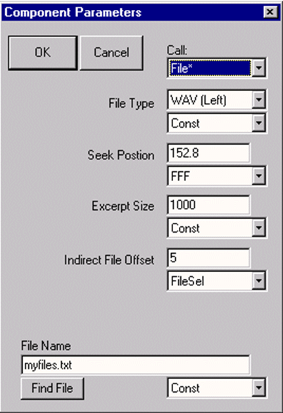
Myfiles.txt contains the following text:
1234567.123
f1k_cat.wav
f1k_dog.wav
f1k_mou.wav
f1k_frg.wav
f1k_bat.wav
f1k_zea.wav
The WAV file accessed will be f1k_bat.wav. 1000 points will be read starting at point 152 and if the file is stereo, left channel data will be returned. Note that the first line is not used, and all lines have the same number of characters.
File16 and File* are very useful ways to generate waveform components which cannot be easily produced with simple mathematical functions. Combined with SigGenRZ variables, you can assign several binary files to the same component, and use a certain file for a certain interval based on the variable values.
When a File* file is read to SigGenRZ in time domain, the values of the data points will be taken in terms of Volts and no conversion will be performed.
The Frequency Options
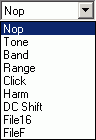
Components generated from Frequency Method are periodic waveforms. Each "period" of the waveform includes the same number of points of inverse FFT (specified as Freq[####] in Edit Segment Parameters dialog box). One "period" of the generated tone has an integer number of complete cycles. So, generated noises may appear periodic due to this inverse FFT technique. You may want to select a different number of iFFT points to produce a satisfactory signal.
Nop: Causes no operation to be performed, so no component will be defined. Choosing Nop for an existing component causes the component to be removed from the segment.
Tone: Produces a pure tone waveform from frequency domain. Parameters include:
-
Level in dB
-
Phase (cosine) in radians
-
Frequency in Hz
Band: Produces a noise of a specific bandwidth around a center frequency. Parameters include:
-
Low frequency level in dB: The lower end level of the band. This level is per Hz average level.
-
High frequency level in dB: The higher end level of the band. This level is per Hz average level.
-
Center frequency in Hz: The geometric center frequency. The high and low frequencies are calculated based on following:
FH = FC * 2 ^ (BW/2)
FL = FC * 2^& (-BW/2)
Where: FH is the high frequency, FL the low frequency, FC the center frequency, and BW the bandwidth in Octaves.
-
Bandwidth in Octaves: One Octave is a doubling (or halving) usually in frequency measurements. For example, one Octave from 200 Hz is 400 Hz, while two Octaves is 800 Hz, and so forth. This value must be greater than zero. A zero will produce a tone, and a negative value will generate an error message.
-
Roll-off in dB/Octave: The roll-offs at the band boundaries. A negative value specifies a roll-off, while a zero or positive value sets the roll-off to be infinite.
-
Range: Produces a noise of a specific frequency range. Parameters include:
-
Low frequency level in dB: Magnitude spectral level at the lower end of the range.
-
High frequency level in dB: Magnitude spectral level at the higher end of the range. Levels at other frequencies will be linearly interpolated.
-
Low frequency in Hz
-
High frequency in Hz
-
Roll-off in dB/Octave
Click: Produces a bi-level click from frequency domain. Parameters include:
-
Low frequency level in dB
-
High frequency level in dB
-
Low frequency in Hz
-
High frequency in Hz
-
Roll-off in dB/Octave
Harm: Produces a spectrum composed of a fundamental frequency and several of its harmonics. Parameters include:
-
Fundamental frequency level in dB
-
Fundamental frequency in Hz
-
Frequency separation in Hz: Distance between the frequency components.
-
Roll-off in dB/component: The magnitude reduction rate in dB per component. A positive number indicates an increase in magnitude.
-
Number of components: Unity means only the fundamental component (tone); zero indicates infinite number of harmonic components. A negative number is invalid, and may crash your system.
DC Shift: Produces a DC offset in frequency domain. Parameters include:
- Level in dB: Since a DC-offset in spectrum is the same level of DC offset in time signal, this level is both time and frequency domain DC offset level. (See The Time Options if you want to generate a negative DC Shift)
File 16 and FileF: These options allow you to define a component based on one or a group of header-less, 16-bit integer binary files or binary floating point files. When you use a group of files, the file extensions must be three-digit numbers (for example, five possible file names: file.005, file.004, file.003, file.002, file.001, and only file.000 should be entered in the parameter field). Parameters include:
-
File name (filename.000 for more than one file)
-
File extension variable. If there is only one file, Const should be selected. If more than one file will be used, a variable must be selected, and the variable values must be the three-digit numbers of the file extensions.
The frequency and phase data should be interleaved (freq, phase, freq, phase ...). The level of each frequency bin is specified in dBVolts and the phase in degrees (0 to 360).
The values of the frequency bins should be set to something like -250 if you don't want sound, and 0 if you want sound (for example, a 0 in one bin would produce a 1 V tone). It is important that you have the same number of frequency points and phase points as you have points in your FFT. For example, if you use a 1024-pt FFT, your file should contain 2048 points (1024 freq points, and 1024 phase points). If it is too short, SigGenRZ will include a bunch of zeroes at the end, which results in a large unwanted signal. If you have too many points, SigGenRZ will use the number of points of the specified FFT, and ignore the remaining values. Note, this will ignore the calibration you set in SigGenRZ (e.g. 9 V = 180 dB).
Note
Entering 0 for Roll-off in dB/Octave will result in the computation of infinite roll-off.
Note
In both time domain and frequency domain, data points in File16 and FileF files must have the same sampling period as the signal you are designing.
Importing Components
SigGenRZ signals can be created using existing non-SigGenRZ digital signals. SigGenRZ signals are built from segments. Segments are built from components. A non-SigGenRZ signal, therefore, must be imported as a component.
Imported waveforms may be specified in either the time or frequency domains. Refer to the above sections for designating file extensions.
Importing Time-Domain Waveforms
Time-domain waveforms may be imported for a variety of reasons.
-
Including the waveform as one segment of a multi-segment signal.
-
Adding the waveform to another component or segment.
-
Multiplying another segment by the imported waveform.
To import a time-domain component:
-
If you want to import more than one file, define a variable which will have values equal to the file extension digits while SGI is increasing.
-
Access the Edit Signal Segments window.
-
Choose Time from the Generation Method list box.
-
Click one of the three Component buttons to access the Components Parameters dialog box.
-
Choose the desired File command from the Call Drop-down box.
To import a 16-bit integer binary file:
- Choose File16.
To import another file type:
-
Choose File*.
-
Type in the file name in the File field. The file extension must be .000.
-
If you want to import more than one file, select the file extension variable in the variable list.
-
Click the OK button.
Importing Frequency-domain Waveforms
You may wish to import a component defined in the frequency domain. An imported frequency domain waveform may be used to:
-
Generate a time-domain component waveform with spectral characteristics that remain constant over time.
-
Apply spectral shaping to other SigGenRZ components.
To import a frequency-domain component:
-
If you want to import more than one file, define a variable which will have values equal to the file extension digits while SGI is increasing.
-
Access the Edit Signal Segments window.
-
Choose Time from the Generation Method list box.
-
Click one of the three Component buttons to access the Components Parameters dialog box.
-
Choose the desired File command from the Call drop-down box.
To import a 16-bit integer binary file:
- Choose File16.
To import a floating point binary file:
-
Choose FileF.
-
Type in the file name in the File field. The file extension must be .000.
-
If you want to import more than one file, select the file extension variable in the variable list.
-
Click the OK button.