Signal Segments
When you are designing signals in SigGenRZ, you are actually designing sub-signals, segments, and specifying how each segment is related to any others temporally. You are also specifying how a segment will affect the entire signal. This chapter introduces Segment design and its characteristics.
Segments, in turn, are composed of one to three components. From the Edit Signal Segments window, you can define segment components.
The Segment Window
The Edit Signal Segments window allows you to specify all the parameters necessary for the definition of a segment.
To access the Edit Signal Segment window:
- Select Segment from the Modify menu of the main window.
or
-
Click the Modify Segment
 button.
 -
Double-click the desired segment marker.
Note
Double-clicking a segment marker will prompt the signal segment window for that segment.
Creating/Selecting/Deleting a Segment
Select
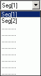
Existing segments are listed in the Select drop-down combo box.
To select an existing segment:
- Click the desired segment in the Select box.
New
When you start to design a new signal, there is only one segment (empty) for the signal. You may need to create new segment(s) to complete the signal. New segments must be created in the Edit Signal Segment dialog box.
To create a new segment:
- Click the New button.
Delete
A segment can be removed (deleted) from the signal.
To delete a segment:
- Click the Delete button.
Note
A signal must contain at least one segment. You may not delete the last segment of a signal. If you wish to clear the entire signal, return to the SigGenRZ main window and close the unwanted signal window.
Segment Generation Options
Windowing/Gating Parameters
Gate Type

From the Gate Type box, you can select a variety of gating or windowing functions, including:
In cases where gating or windowing is not necessary (e.g., click generation), choose None.
Gate Time
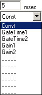
Gate Time specifies the rise/fall times of the gating function in milliseconds.
Constant or Variable Gate Time:
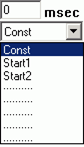
By default, Gate Time is defined as Const, and therefore remains constant throughout the preview process, regardless of the current SigGen Index value. Gate Time may be varied as a function of the current SigGen Index value by assigning a predefined variable (see Creating Variables.
To set Gate Time to a constant or a predefined variable:
- Click Const or the desired variable name in the Gate Time box or if Gate Time is a constant, enter the value in the Gate Time field.
Signal Parameters
Gain
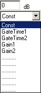
The Gain field of the Edit Signal Segments window is used to adjust the overall level of the digital segment generated by SigGenRZ. All components of this segment are affected by this value.
Note
Gain is measured in dB. The reference level for dB is user defined. See Calibration for more information.
Note
The RZ6 processor limits the Voltage range to ±10 V. Clipping will result during signal play if Voltages exceed this range. If Voltages of the segment, as displayed in the Time Form window of the Edit Signal Segments screen, exceed ±10 V, lower the gain value. You may have to lower the level of one or more of the segment's components to obtain a correct segment level. In contrast, when the Voltage of the segment is too small, signals will not be correctly presented at the D/A converter even if the segment is smoothly displayed on the segment Time Form plot. If this segment is the dominant one in the signal, audible noise may appear. When this happens, you must increase the gain value to suppress noise, and use the on-board attenuator to adjust the signal.
Constant or Variable Gain: By default, Gain is defined as Const, and therefore remains constant throughout the preview process, regardless of the current SigGen Index value. Gain may be varied as a function of the current SigGen Index value by assigning a predefined variable. See Variables for more information.
To set Gain to a constant or a predefined variable:
- Click Const or the desired variable name in the Gain box or if Gain is a constant, enter the value in the Gain field.
Start
The value defined in the Start field defines the delay of the segment onset in the signal in milliseconds.
Constant or Variable Start: By default, Start is defined as Const, and therefore remains constant throughout the preview process, regardless of the current SigGen Index value. Start may be varied as a function of the current SigGen Index value by assigning a predefined variable (see Variables. You can arrange segments in various manners by assigning different Start values (or variables) for each segment.
To set Start to a constant or a predefined variable:
- Click Const or the desired variable name in the Start box or if Start is a constant, enter the value in the Start field.
To set the Start value to the beginning of the signal:
- Click the To Begin button found in the segment dialog box.
Duration
The value of the Duration field defines the total duration of the segment in milliseconds.
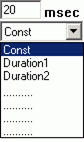
Constant or Variable Duration: By default, Duration is defined as Const, and therefore remains constant throughout the preview process, regardless of the current SigGen Index value. Duration may be varied as a function of the current SigGen Index value by assigning a predefined variable. See Variables for more information.
To set Duration to a constant or a predefined variable:
- Click Const or the desired variable name in the Duration box or if Duration is a constant, enter the value in the Duration field.
Note
Start and Duration values should not fall outside of the signal duration. If this happens and you do not correct it, SigGenRZ issues a warning, truncates the segment, and continues.
To set the Duration value to the entire length of the signal:
- Click the To Max button found in the segment dialog box.
Generation Method

Gen. Meth (Generation Method)
You must specify how the segment (its components) is generated by SigGenRZ when you design the signal. SigGenRZ uses two basic generation methods: Time and Frequency. The Time method generates signal components by calculating their time waveform points. Frequency methods specify their frequency characteristics first, and use inverse FFT to obtain the waveform points. Depending on the frequency resolution, there are several Frequency method options.
To choose a Generation Method:
- Click on the Gen. Meth. Drop-down box and click on the desired Generation Method in the Generation Method combo box.
When to Use a Frequency Domain Generation Method
Generating signals in the frequency domain allows you to specify the frequency components of your signal. Some signals (tone, click, Gaussian noise, DC shift) can be generated from time domain or frequency domain, while others (band-limited noise, harmonics) can only be generated from frequency domain. Usually when you want to generate band-limited noise, harmonics, or to specify the frequency contents of a signal, you may consider using frequency method.
Choosing Among the Frequency Options
SigGenRZ generates time-domain waveforms from frequency parameters through the use of the inverse Fast Fourier Transform (iFFT). The iFFT builds signals based on a finite number of frequency components (FFT points, which must be a radix-2 number). A list of frequency options is displayed in the Generation Method box.
The number of combined magnitude and phase spectra FFT points is indicated in parentheses. To determine the number of either magnitude or phase spectra FFT points, simply divide this number by 2.
Choice of the number of FFT points depends on the sample period you have defined for the time-domain waveform and the desired binwidth, or distance between two adjacent points in the signal spectrum in Hz.
Number of FFT points = 1 / (binwidth x sample period)
To choose a frequency option:
-
Calculate the desired number of FFT points using the above equation.
-
Choose the frequency option with a combined number of magnitude and phase FFT points greater than 2 times the number calculated in (1) to ensure a minimum binwidth. Since there are only a limited number of points for inverse FFT, the signal generated may not be enough to cover the duration of the segment. SigGenRZ repeats the same iFFT result to obtain enough points.
Application Method
App. Meth (Application Method)
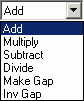
Segments may be applied to the existing signal in one of several ways:
-
Add: A segment may be added to the existing signal.
-
Multiply: A segment may multiply the existing signal.
-
Subtract: Subtract a segment from the existing signal.
-
Divide: Divide the existing signal by the segment.
-
Make Gap: Creates a gap in the signal, based on the segment.
-
Inv Gap: Creates an inverse gap in the signal, based on the segment.
Note
The RZ6 D/A converters limit the Voltage range to ±10 V. Clipping will result during signal play if Voltages exceed this range. If this occurs, the overall signal, as displayed in the Signal Window of the SigGenRZ main window, will appear clipped. When this occurs, some modification of segment level or component level will be necessary.
To choose an Application Method:
- Click the desired method from the Application Method box.
Using Application Method to Build the Signal
Two Application Method options are designed to help build or modify a signal:
-
Add
-
Subtract
Add is used primarily to build a signal by adding together two or more segments. For example, a noise segment can be added to a signal to reflect the background noise.
Subtract is used primarily to remove unwanted signal components from the signal. For example, DC offset has to be specified in decibel values, so only positive DC offset can be produced in a segment. A negative DC offset can be generated by subtracting a DC offset from a signal.
Note
Segments consist of one or more components. Components are always additively applied to the segment. As part of component definition, it is necessary to define a component level. When using the Application Methods Add or Subtract, component level is defined in terms of the system calibration specified during signal parameter definition.
For example, if system calibration is defined as 90 dB equal to 9 Volts, specifying a 90 dB tone will result in a tone whose peak amplitude is 9 Volts.
Using Application Method to Modulate the Signal
Several Application Method options allow you to modulate the current signal:
-
Multiply
-
Divide
-
Make Gap
-
Inv Gap
Note
Segments consist of one or more components. As part of component definition, it is necessary to define a component level. When using the modulating Application Methods presented above, component level is NOT defined in terms of the system calibration specified during signal parameter definition, but is instead defined as 0 dB equal to 1 Volt. Thus, specification of a tone with a level of 0 dB will create a tone with a peak amplitude of 1 Volt.
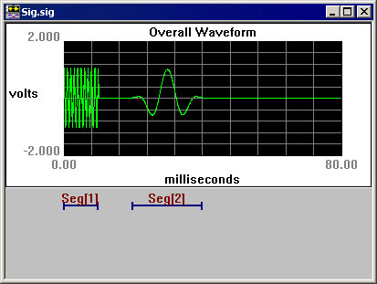
The segment waveform generated will be displayed at the bottom of the Edit Segment Parameters dialog box in both Time Form and Magnitude Spectrum. The waveform can be previewed and updated in this box. See Working with Segments for detailed information.
Segment Repeating
To support the production of stimuli with multiple pulses, SigGenRZ supports segment repeating. The exact number of repeats and each of the repeats' temporal position are controlled by three new parameters within the Segment edit dialog box.
The Repeats, RepSep, and Freeze Repeats options are used to control Segment repeating. When Repeats is set to zero or one, a single copy of the generated segment will be applied to the overall signal. Making the Repeats parameter two or more will cause the segment to repeat across the signal with a start-to-start separation of RepSep milliseconds between each segment onset.