The Test Equipment
The care used in setting up your test area must also be taken when selecting and setting up your test equipment. TDT's DPOAE system is part of a modular experiment platform. Each module in the system is designed for exceptional signal fidelity, precise timing, low noise, and ease of use.
The sub-sections below discuss the role each part of the system plays in running a DPOAE experiment and provides information on making the necessary connections.
DPM1
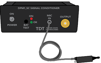
The DPM1 is a DPOAE microphone system manufactured by TDT. It can detect low intensity signals in the range of 0 Db SPL. It can detect signals out to about 40 kHz.
The provided cable and Ear Tip carry the response from the microphone into the system via a front panel BNC output.
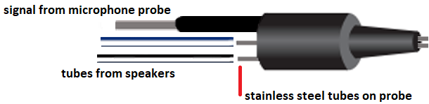
The microphone tip also has two small tube-connectors to carry the stimuli to the subject's ear. Slide the closed-field speaker tubes over these small stainless steel tubes, ensuring a snug fit.
Note
Check Ear Tip for obstructions before using. It can become plugged with debris from the subject, reducing the measured DP.
See Speaker Placement for information on how to position the ear tip.
Speakers
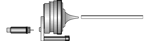
TDT's MF1 Multi-Field Magnetic Speakers are suitable for testing in the hearing range of mice and rats. They should be configured for Closed Field for DPOAE testing (see Configuring the MF1 for Closed Field Operation). Each MF1 comes with a tapered tube tip that mates with the provided ⅛" outside diameter PVC tubing (10 cm included). Always use the shortest tube possible to avoid bending or crimping. You can cut the tube to the desired length, typically 3-5 cm. The tube should slide snugly into the tube tip. You can push firmly without fear of damaging the tube. If you have trouble inserting the tube, spray a small amount of silicone lightly on a cloth, then put the tip of the tube on the cloth to apply it.
Warning
Other lubricants (WD-40, grease sprays, or similar) should not be used as they can damage the O-rings surrounding the tube tip, or the tubes themselves.
The MF1 comes with an inline filter (pictured to the left of speaker, above) that connects between the RCA cable and speaker input. This filter should always be in place when using the MF1 speakers in closed-field mode. In this mode, the MF1 has undesirably high, low-frequency output. This filter reduces the speaker output at low frequencies so that the output range can be equalized.
Each MF1 has a built-in 8-32 threaded hole for use with standard laboratory mounting hardware. Some mounting hardware is included with the MF1.
Note
The EC1, Closed-Field Electrostatic Speakers can be used for higher frequency studies.
RZ6 Signal Processor
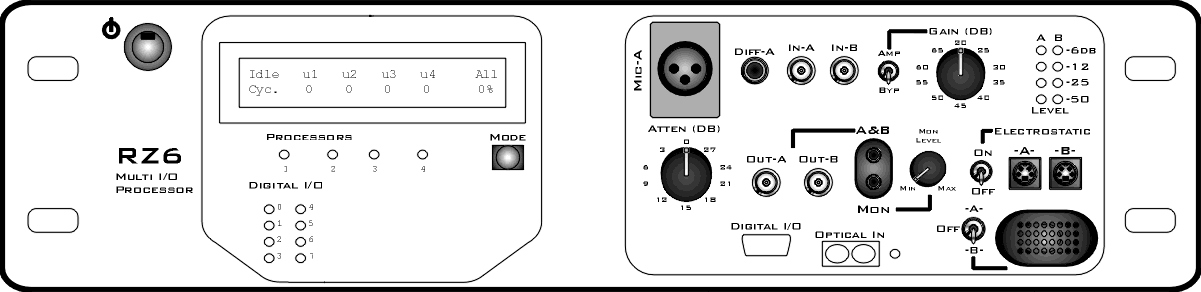
The RZ6 Multi I/O Processor provides the processing power for averaging signal inputs and the digital-to-analog converters and amplifiers for producing the stimuli. It also provides the precise timing essential to evoked response experiments. The power input and optical connection to the PC are located on the back. The input/output support (such as speaker drivers) and attenuation that is incorporated into the device are all accessed on the front panel.
Stimulus Output
The RZ6 can generate a stimulus in the frequency range of DC - 88 kHz and is well suited for standard DPOAE testing.
A built-in stereo power amplifier drives the stimulus signals through TDT's MF1 multi-function speakers via the BNCs labeled Out-A and Out-B.
Use RCA - BNC cables (included with the MF1 kit), or BNC to RCA adapters, to connect OUT-A and OUT-B to the RCA connectors on the speakers.
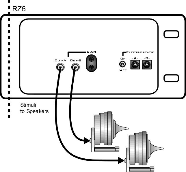
Important
When using the MF1s, the ON/OFF switch next to the outputs marked Electrostatic must be in the OFF position to reduce noise.
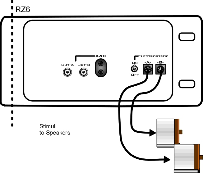
If using EC1 speakers, the ON/OFF switch next to the outputs marked Electrostatic must be in the ON position.
Attenuation
Typically, stimulus attenuation is handled via software. The Atten knob on the front panel provides optional manual attenuation applied to the signal before it is output. This can be useful if the sound level is found to be systematically too high across all frequencies during speaker calibration. See DPOAE Calibration.
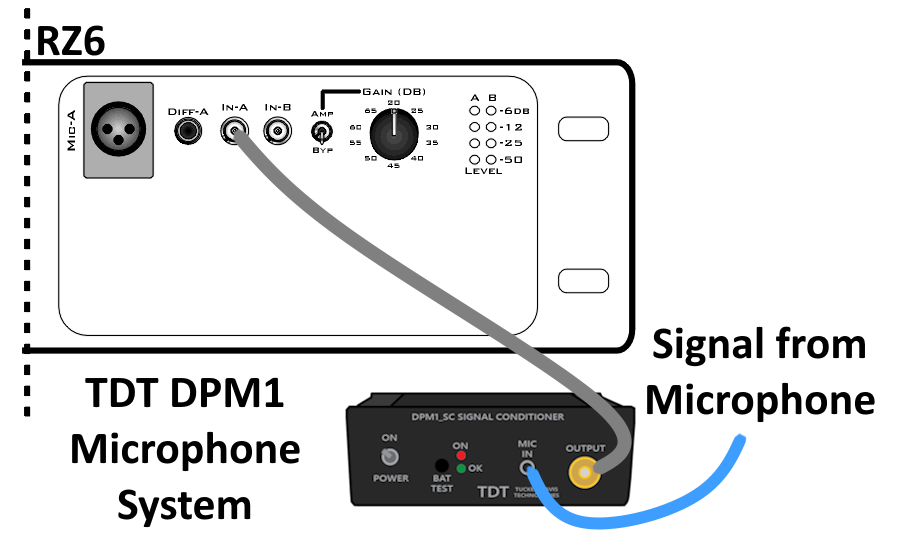
Mic Inputs
Connect the DPM1 Out to the Microphone In-A BNC input connector. No gain is required for the signal, so the AMP/BYP switch must be set to BYP.
PC and Interface
The RZ6 must be directly connected to a PC, which provides the user interface for the system. The PO5 or PO5e optical interface card is installed in the PC and connected to the RZ6 across fiber optic cables. This adds another layer of noise reduction, isolating the processor from the noisy PC environment.
The PC handles:
-
Configuring the hardware and software.
-
Communicating with the TDT hardware and transferring data across a fiber optic interface.
-
Displaying and working with data during and after acquisition.
If you use TDT's WS4 computer, the optical interface and BioSigRZ software are preinstalled.
If you use your own PC, you'll need to install the interface card and BioSigRZ software yourself. Step-by-step instructions for installing software and drivers and setting up the processor are available in the System 3 Install Guide that came with your system. The installation guide also includes information for connecting the WS4 or your PC to the RZ6 Processor, including running a transfer test to ensure communication between them is working correctly.
Note
A UZ3 (USB 3.0) interface is also available if you wish to use a laptop.