RZ2 BioAmp Processor
RZ2 Overview
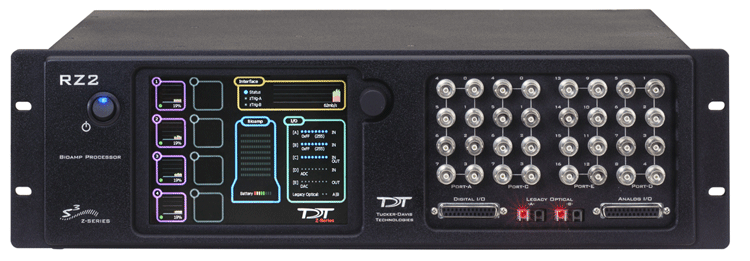
The RZ2 BioAmp Processor has been designed for high channel count neurophysiology recording and signal processing. The RZ2 features two (RZ2-2), four (RZ2-4), or eight (RZ2-8) digital signal processors cards. Any card can be either a single standard processor card (RZDSP) or a quad-core processor card (QZDSP). Standard single processor cards use a single Sharc DSP; quad-core processor cards use four Sharc DSPs Cores with the potential to more than double the power of the RZ2.
All cards are networked on a multiprocessor architecture that features efficient onboard communication and memory access. The highly optimized multi-bus architecture uses four dedicated data buses to eliminate data flow bottlenecks - all transparent to the user. This architecture yields an extremely powerful system capable of sophisticated real-time processing and simultaneous acquisition on all channels.
The RZ2 is typically used with a Z-Series Amplifier (such as the PZ5). High bandwidth data is streamed from the amplifier to the RZ2 over a lossless, fast, fiber optic connection. Both single and quad-core processors cards may include an optical interface for connection to devices such as the RS4 Data Streamer, an IZ2 Stimulator or a secondary PZ Amplifier (see Specialized Interface Boards for more information).
Each onboard optical connection can support 256 channels at sampling rates up to ~25 kHz and 128 channels at sampling rates up to ~50 kHz. The RZ2 also features 16 channels of analog I/O, 24 bits of digital I/O, two Legacy optical inputs for Medusa PreAmps, and an onboard LCD for system status display.
Power and Communication
The RZ2's Optibit optical interface connects to a PO5, PO5e, PO5c, or UZ3 computer interface card for fast and reliable data transfer from the RZ2 to the PC. Connectors on the back panel are color coded for correct wiring.
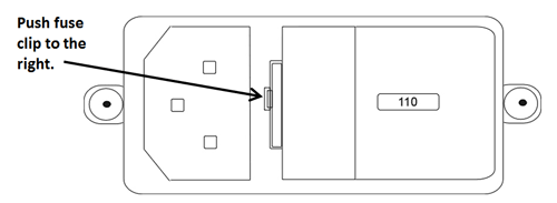
The RZ2's integrated power supply is shipped from TDT configured for the end user's regional voltage setting (110 V or 220 V). If you need to change the voltage setting:
-
Turn off the RZ2
-
Use a small flathead screwdriver to gently push the clip along the left side of the fuse plate to the right to remove it.
-
Remove the white AC voltage selector and rotate it until the desired voltage is displayed, then reinsert it and put the fuse plate back on.
The RZ2 is UL compliant, see the RZ2 Operator's Manual for power and safety information.
Software Control
TDT's Synapse software controls the RZ2 and provides users a high level interface for device configuration.
RZ2 TouchScreen
The touchscreen shows information about each DSP, the optical PC interface, a connected PZ preamplifier, and system I/O.
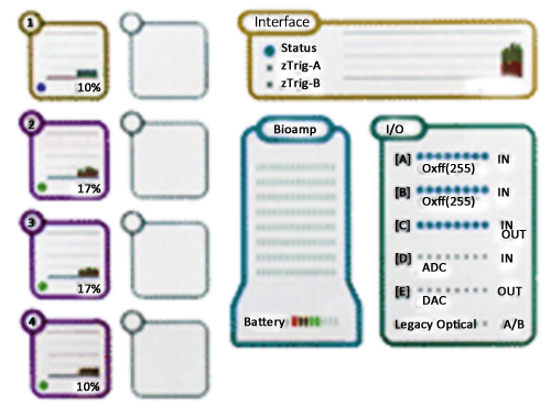
Touch a section of the screen to display more detailed information.
DSPs
A stacked bar plot shows cycle usage for each DSP with the bottom section (blue) showing
the cycle usage taken up by circuit operation and the top section (pink) showing the cycle
usage required for data transfer.
If the cycle usage surpasses 100%, a bar is drawn
above the 100% line in the cycle use bar plot and will persist until the RZ2 is rebooted.
For quad-core DSPs, the core with the highest cycle usage is displayed.
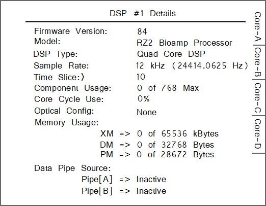
Optical Config is the peripheral device supported by the DSP, if any.
Data memory (DM) is the amount of DM used for filter delay line and short delays.
External Memory (XM) is the amount of XM used for long delays and buffers.
Program Memory (PM) is the amount of PM used to hold filter coefficients.
Tabs are enabled for quad-core DSPs, with one Core per tab.
Interface
Virtual Status lights display status of the interface (Status), zTrig-A, and zTrig-B. A stacked bar chart shows data transfer rate in MB/s.
Touch to Display: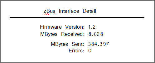
Firmware version, MB data received/sent and transfer errors.
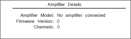
Amp
Touch to Display: Amp model, number of channels and firmware version of connected PZ series amplifier to dedicated 'PZ Amplifier' fiber optic port on the back of the RZ2.
I/O
Virtual indicator lights.
[A], [B], and [C]: Digital I/O, LED will light for an input bit or it will show the logic level for an output bit.
[D] and [E]: Analog I/O, 16 lights indicate the signal level, green when a signal is present and red to warn that the signal is approaching the maximum voltage (at which point clipping would occur).
Legacy Optical: Amp Light For The Legacy Preamplifier Sync, Flashes yellow when no amp is connected and will be light green when the amplifier is correctly connected.
Note
Older versions of the RZ2 have a selection knob that allows the user to highlight a section of the screen. To display more detailed information, rotate the knob to select a system component and then push the knob to show the information view.
RZ2 Architecture
The RZ2 processor uses a highly optimized multi-bus architecture and offers four dedicated data buses for fast, efficient data handling. While the operation of the system architecture is largely transparent to the user, a general understanding is important when designing experiments.
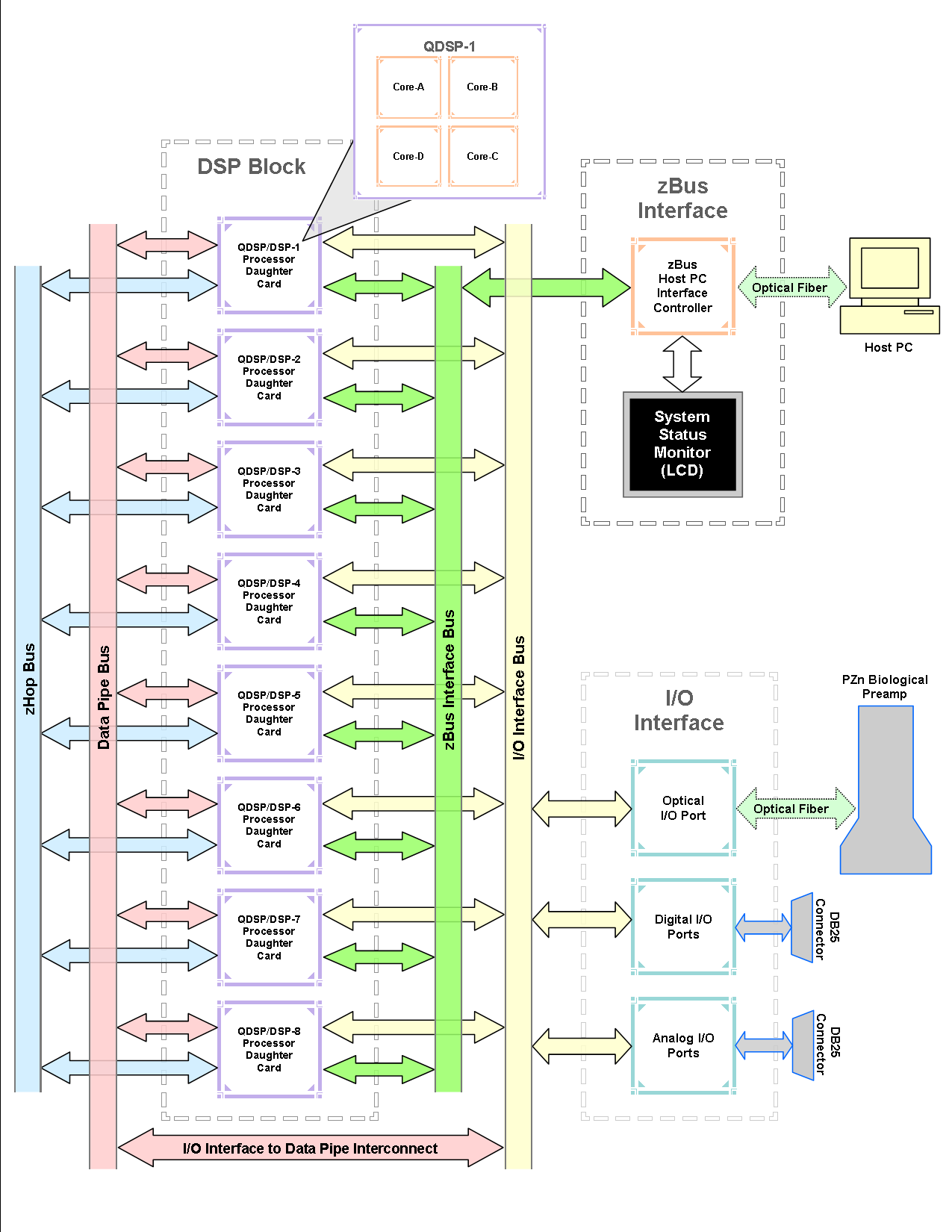 |
| RZ2 Multi-DSP Architecture Functional Diagram |
As shown in the diagram above, the RZ2 architecture consists of three functional blocks:
For the best performance, processing tasks must be efficiently distributed across the available DSPs. Synapse software automatically handles this. For custom circuit programming, see the RPvdsEx manual.
Bus Related Delays
A standard two sample delay is associated with the zHop, and Data Pipe. However, these delays are managed for the user in Synapse software.
50 kHz Sampling Rate Acquisition with the PZ Amplifier
The RZ2 and PZ amplifier support sample rates from ~6 kHz to ~50 kHz. When sampling at a rate of ~50 kHz, only the first 128 PZ amplifier channels will be available.
Data Transfer Rate
As with other devices, your expected sustained RZ-to-Host PC data rate should not exceed ½ to ⅔ of the rated data transfer speed. For the RZ2 device this is 160 Mbits/second (Mbps) so your designs should have a sustained data rate of no more than ~100 Mbps. When the RZ2 is processing, the current data transfer rate (Mbps) is displayed in the top right corner of the LCD Screen. This maximum rate may be further limited by your PC's ability to store the data to disk.
RZ2 Features
Amplifier and Onboard Analog I/O
The RZ2 is equipped with both optical port amplifier input and onboard analog I/O capabilities. The high speed fiber optic port (located on the RZ2 back panel) allows a direct connection to a PZ5 amplifier. The Legacy fiber optic ports on the front panel allow a direct connection to Medusa preamplifiers. Physiological signals are digitized on the preamplifier and transferred across noiseless fiber optics.
The RZ2 also includes onboard D/A for stimulus generation and experiment control, and A/D for input of signals from a variety of other analog sources.
The table below provides a quick overview of these I/O features and how they must be accessed during experiment design.
Onboard Analog I/O
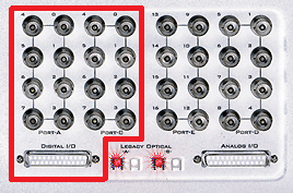
The RZ2 is equipped with eight channels of 16-bit PCM D/A and eight channels of 16-bit PCM A/D. All 16 channels can be accessed via front panel BNCs marked Port D and Port E or via a 25-pin analog I/O connector. See DB25 Analog I/O Pinout and BNC Channel Mapping.
PZ Amplifier Fiber Optic Port
This is the RZ2's primary amplifier input and is located on the back panel. The connectors on the fiber optic pair used for PZ amplifier communication are color coded for correct wiring. This port can read up to 256 channels at a maximum sampling rate of ~25 kHz or 128 channels at a maximum sampling rate of ~50 kHz.
Legacy Fiber Optic Ports
The RZ2 station has two Legacy fiber optic ports labeled -A- and -B- to acquire digitized signals from the Medusa4Z, RA16PA, RA8GA, or HTI3 interface. Each port can read up to 16 channels at a maximum sampling rate of ~25 kHz.
Digital I/O
The digital I/O ports include 24 bits of programmable I/O. The digital I/O is divided into three ports (A, B, and C) as described in the chart below. All digital I/O lines are accessible via the 25-pin connector on the front of the RZ2 and ports A and C are available through BNC connectors on the front panel. See DB25 Digital I/O Pinout and BNC Channel Mapping. If using a PP24 Patch Panel, see PP24 to RZ2 Digital I/O.
The digital I/O is configured in the Synapse RZn Hal.
The data direction for the Digital I/O is also configured in the Synapse RZn Hal.
The RZ digital I/O ports have different voltage outputs and logic thresholds depending on the type. The table below depicts the different voltage outputs and thresholds for both types.
UDP Ethernet Interface
The RZ UDP Ethernet interface can transfer low bandwidth data directly to or from a PC. RZ devices equipped with a UDP interface have an additional Ethernet port and RS232 serial port located on the back panel. See RZ-UDP Communications Interface for more information.
Note
If the RZ2 has 4 optical DSP cards (see below) installed, the RS232 serial port is not available.
Specialized DSP/Optical Interface Boards
The RZ standard DSP boards can be replaced with specialized DSP boards which include an optical interface for communication and control of RZ compatible devices, such as the Subject Interface and RS4 Data Streamer. RZ devices equipped with one or more specialized DSP boards include an optical port for each card. The ports are located on the back panel and labeled for easy identification.
RZ2 Technical Specifications
Note
Technical specifications for preamplifier A/D converters are found in the specific preamplifier document.
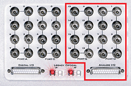
BNC Channel Mapping
Please note channel numbering begins at the top right block of BNCs for each port and is printed on the face of the device.
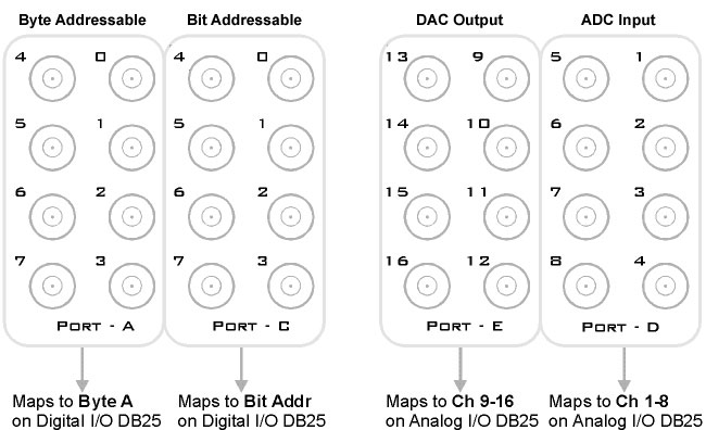
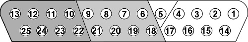
DB25 Analog I/O Pinout
DB25 Digital I/O Pinout
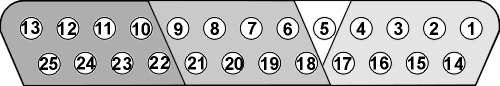
If using a PP24 Patch Panel, see PP24 to RZ2 Digital I/O.