RA8GA Adjustable Gain PreAmp
RA8GA Overview
The RA8GA acquires and digitizes multi-channel data from a variety of analog voltage sources such as eye-trackers, amplifiers (including Grass, Axon, and WPI amplifiers), PH meters, and temperature sensors. The RA8GA digitizes up to eight channels at acquisition rates of 6, 12, or 25 kHz. All channels have a variable group gain setting of 10 Volts, 1 Volt, or 100 millivolts. The system has a bandwidth to DC, which allows users to acquire low frequency DC signals. In addition a two-pole low pass filter (12 dB per Octave) is set at 7.5 kHz.
Power and Interface
The device is powered via the System 3 zBus (ZB1PS) and requires an interface to the PC. If the RA8GA is housed in one of several ZB1PS chassis in your system, ensure that it is connected in the interface loop according to the installation instructions: Gigabit, Optibit, or USB Interface.
RA8GA Features
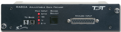
Max Input Lights
The Active light flashes once a second when the preamplifier is not connected to a base station. It glows steady when it is properly connected.
The 10 V, 1 V, and 0.1 V lights indicate the current acceptable voltage range. If the signal input reaches -6 dB from the maximum input for the selected range, a clip warning light on the base station will be lit. On RX5 or RX7 processors the LED located next to the fiber optic input port serves as the clip warning light.
Range Select Button
All channels use a group adjustable gain control i.e. all channels are either ±1 Volt, 10 Volts, or 0.1 Volt. A Range Selection button adjusts the gain setting among the following voltages: 0.1X gain = ±10 V, 10X gain = ±100 mV, 1.0X gain = ±1 V. Press the button to scroll through the available voltage ranges. Max input lights located to the left of the button, indicate the current selection.
To Base
The To Base connector is used to connect the device to the base station (such as RZ5, RZ2) using a fiber optic cable pair. One end of the fiber optic cable connects to the device using this connection pair and the other end connects to the input on the base station.
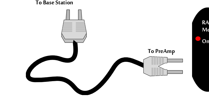
Connecting the Base Station to the Preamplifiers
To make the connection, plug one end of the cable into one of the fiber optic connectors as shown below and connect the other end of the cable to the fiber optic port on the base station. Both ends of the cable are the same but the two sides of the connector are different. See the diagram below to determine the correct way to make the connection for each device.
 |
| Medusa PreAmp Connection Diagram |
Analog Input
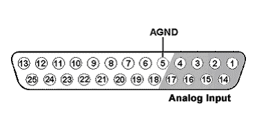
Each Preamp comes with eight channels of analog input. Each analog input uses 16-bit PCM parts for high quality signal conversion. See the RA8GA Technical Specifications for a Pinout Diagram for the 25-pin Analog Input connector.
A PP16 patch panel can be used to simplify connection to the preamplifier's analog inputs. A ribbon cable connects the RA8GA Analog I/O connector to the RA16 connector on the back of the PP16 allowing acquisition of signals via the first eight BNC connectors on the front of the PP16.
RA8GA Gain Settings
Accounting for Gain Settings on the DSP
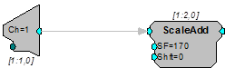
The output from a RA8GA generates a floating-point value of between ±6 mV. A scale factor must be used in order for the acquired signal to display the correct voltage. The scale factor for each gain setting is listed in the table above. The Synapse RAn Hal accounts for this for you. If using RPvdsEx to read the data, the scale factor should be added after the channel input (ADCIn).
The following example shows an RPvdsEx circuit segment that adds the scale factor for a ±1 V input range:
RA8GA Technical Specifications
Analog Input Pinout Diagram