MRI Recording Processor Gizmo
Real-time Artifact Rejection
The MRI Recording Processor gizmo is built into Synapse software. It provides a series of tools for thresholding and removing MRI scanner artifact in single unit and LFP data in real-time during the MRI recording. The MRI Recording Processor gizmo drops in between your signal source and any spike sorting or LFP gizmos.
The gizmo:
- Has adjustable threshold and rejection windows for automatic detection and removal of artifacts in the electrophysiological data stream
- Saves the raw data for offline analysis and artifact subtraction
- Has special filters that reduce ringing after the artifact blanking period has passed, tuned specifically for single unit and local field potential (LFP) signal ranges
- Visualization of neural activity (single unit and LFPs) with and without artifact
The rejection window can be triggered automatically when an artifact is detected or by an external logic signal that syncs to the MRI scanner switching.
See the Synapse Manual for more information.
Configuring the Gizmo
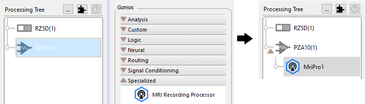
Select the PZ5 or PZA object in the Processing Tree and find the MRI Recording Processor gizmo in the Gizmos list. Drag and drop, or double-click, the gizmo onto the PZ5 / PZA to form a connection.
Note
You can learn more about gizmos and experimental connections in the Synapse Manual.
The MRI Recording Processor has several configuration options for managing how the artifact is detected and gated, and for which type of filtered waveform is output for other downstream processes. In this configuration, a threshold crossing is used to trigger the artifact rejection.
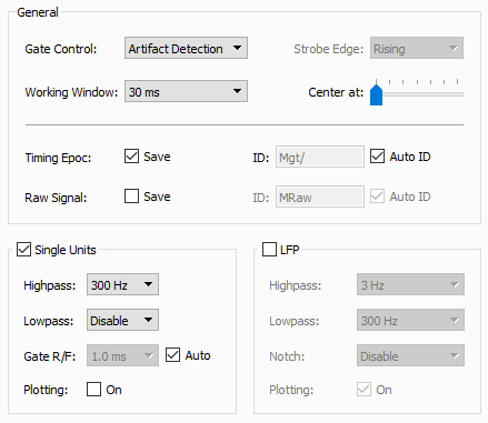 |
| MRI gizmo options for threshold crossing |
Working Window determines how much of the signal to view when an artifact is triggered. Make sure this window is long enough to capture the entire artifact you want to remove.
Optionally save the Timing Epoc to get timestamps when artifacts are detected, stored synchronously with your data as the default epoc event "Mgt/".
You can save the raw signal for offline analysis and artifact subtraction. You can also filter/visualize for Single Unit and/or Local Field Potentials frequency ranges.
Important
Enabling Plotting for Single Unit/LFP shows you the signals from all channels in the flow plot, but does not save the data. Storage gizmos, such as the Stream Data Storage, must be attached to the gizmo output link for saving. Be sure to set the sampling rate appropriately for the bandwidth of data you are trying to capture.
If the MRI has a digital signal that triggers during the scan, this can be connected to the RZ front panel digital input and used to trigger the artifact rejection.
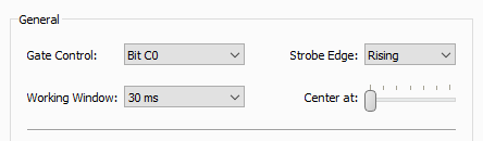 |
| MRI gizmo options for digital input trigger |
Synapse Experiment Setup
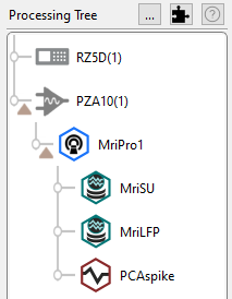 |
| A common processing tree for an MRI recording experiment |
A typical MRI recording setup would look like this. The PZA Subject Interface or PZ5 amplifier routes
raw recording signals to the MRI gizmo for processing and filtering. The outputs for Single Unit and
LFP filter signals are saved in Stream Store Processors at the appropriate sampling rates. If the MRI
has a digital Sync line to mark magnet switching, then a bit input would also be configured in the RZ.
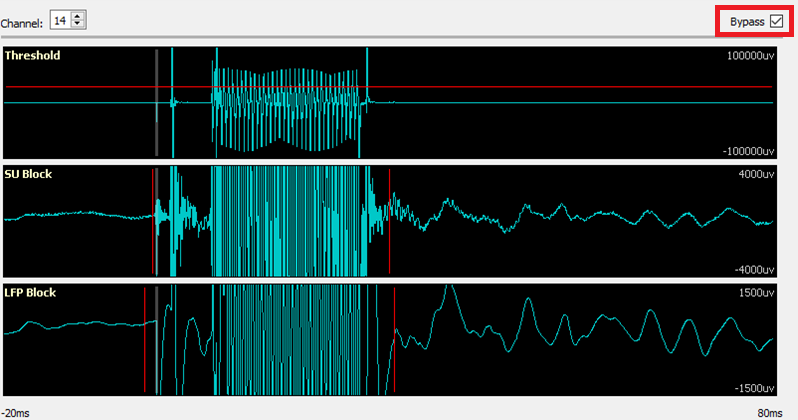
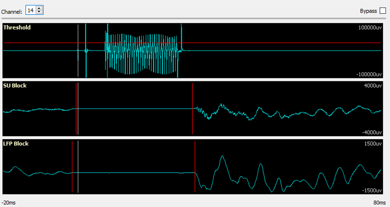
Example Run-Time View
The MRI tab at run-time has the raw signal visualization and selected Single Unit and/or LFP plots. The amount of data is shows is set by the Working Window option during Idle. The gray vertical bar is the start of the artifact. Its location is set with the 'Center At' option.
-
Select a channel with a good representative artifact.
-
Set the artifact rejection threshold in the top plot by click-dragging the red bar. If you don't see the bar, it is outside the current window view. Right-click on the plot and select 'Find Threshold'.
-
Set the bounds of your artifact removal window in the Single Unit and LFP plots by click-dragging the vertical red bars. Single Unit and LFP data are handled differently, due to the different frequency characteristics of these signals, to minimize signal ringing at the end of the removal window.
-
Check that the rejection window works on all channels. There is significant variation in the amplitude of the artifact from channel to channel and also from scan to scan.
Thresholding and filter widths for each signal type can be adjusted during runtime. A threshold crossing on the channel you are viewing is used to trigger the same rejection window on all channels at exactly the same time. If you change the channel, the threshold bar and window stays in the same spot, but now the rejection happens when this new channel crosses the threshold.
You can also bypass the rejection to see the full scanner artifact and signal. This can help in setting up the appropriate rejection window and validating the artifact removal. Check Bypass on the upper right corner of the run-time interface.