Physical Setup and Testing
The headstage cable should be aligned with the center of the bore and extend straight out from the isocenter of the magnet. Make sure the headstage cable is long enough for this.
The amplifier may generate artifacts on the scan if inside the MRI room. Set the amplifier as far away from the scanner as possible. Placing it outside the 5 gauss line is best, if possible. Leaving the amplifier in a strong magnetic field will either cause the batteries to fail or shorten the battery life of the amplifier.
Danger
Connectors on the PZ5 / PZA Subject Interface are ferrous and will be attracted to the magnet. Use extreme caution when handling the amplifier anywhere near the magnet. In general the PZ5 / PZA Subject Interface is heavy enough it won't be pulled into the bore, but it should remain outside the 5 gauss line if possible.
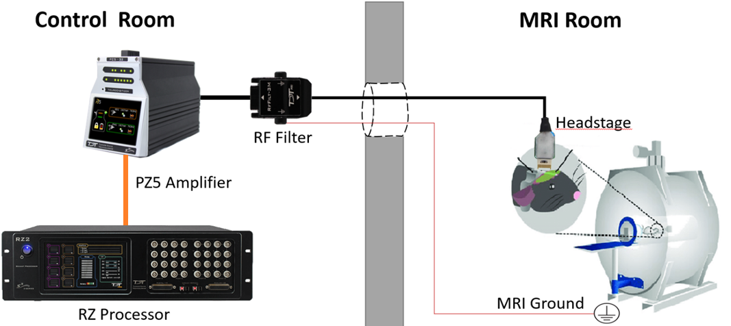
Penetration Panel
The scanner room is well-shielded against radio frequency (RF) noise that affects the image quality. The headstage cable passes from the scanner room to the control room through a penetration panel that may contain RF filters and waveguides.
Penetration panels limit the high frequency signals emitted by the PZ5 / PZA Subject Interface amp. They do not resolve RF noise that is generated along the cable from the PZ5 / PZA Subject Interface amp to the MRI. Any additional RF noise can be filtered with the passive low-pass 50 MHz RF filter that comes with the TDT MRI-KIT. The RF filter is placed in-line between the amplifier and headstage. All wires (recording channels, subject ground, and reference) pass through this filter. This has to be grounded properly to work*. It has a standard 1.5 mm DIN (touch-proof) connectors to connect to the ground on the scanner itself. This then connects to the RZ processor for real-time scanner artifact removal.
Important
*The RF filter ground is different than the subject ground.
Note
The penetration panel and RF filter do not remove scanner artifact from the neural recordings. This is done on the RZ processor in real-time using the MRI Recording Processor gizmo, as discussed in the MRI Gizmo section.
Waveguide
Waveguides are tubes that are a part of the penetration panel. The headstage cables simply pass through. The non-ferrous MRI-compatible headstage is connected to the MRI-compatible electrode. This goes through a very long cable (up to 6-7 m) to the control room to the PZ5 / PZA Subject Interface. Know the length from the bore isocenter to the waveguide when determining what length of cable is needed. The full setup looks like this:
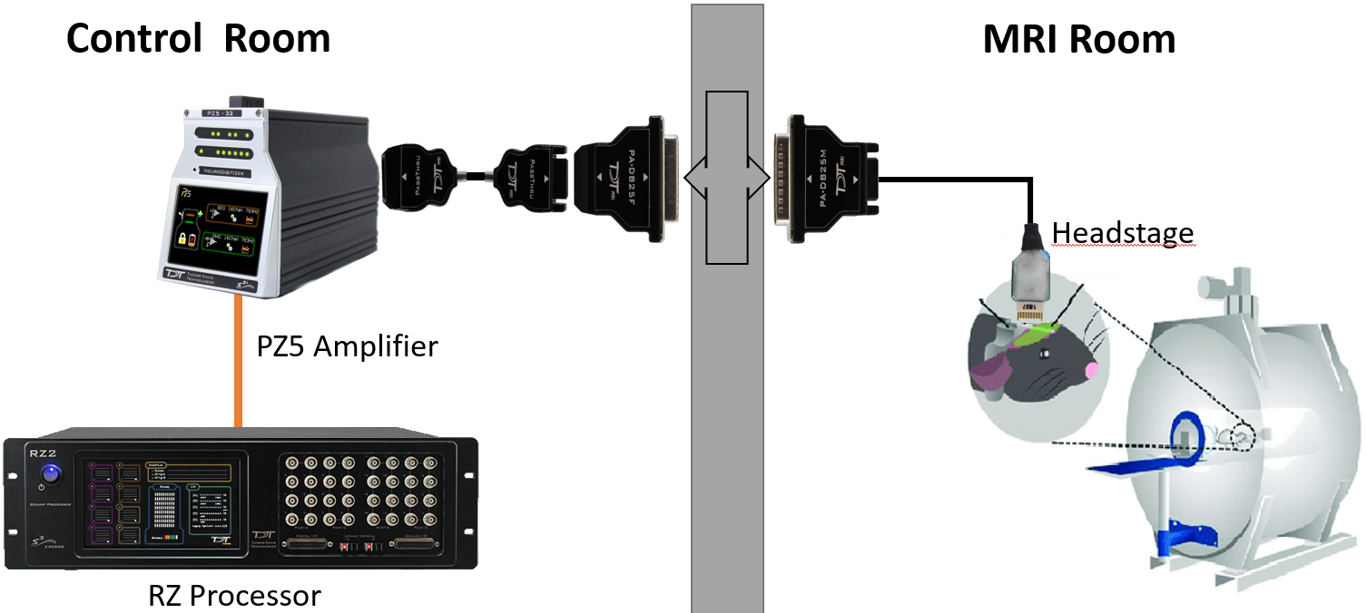
Filter plate
In addition to the waveguide, there is also often a filter plate for BNC and DB25 connectors on the penetration panel to pass signals between the MRI room and the control room. Use the DB25-female and DB25-male connectors provided in the TDT MRI kit to connect the headstage through the filter plate to the amplifier.
Some filter plates are just pass-through connections, in which case you need to use the TDT RF filter in the cable connection.
Minimizing Amplifier Artifact During MRI Scans
We recommend the following setup:
-
Place the PZ5 / PZA Subject Interface amplifier outside the MRI room in the control room or component room. You can place the amplifier on a cart in the control room just outside the penetration panel. All cables pass through either a waveguide on the penetration panel or through a DB25 connector on the panel.
-
Turn off the wifi and the front display screen on the PZ5 / PZA Subject Interface amplifier. See Touchscreen Configuration.
-
Test the system using a phantom with no RF filter. This is your baseline signal.
-
If there is significant artifact connect the RF filter to the back of the PZ5 / PZA Subject Interface amplifier and the GND on the RF filter to either:
a. The MRI GND. This is the GND found on the gradient power supply. This GND is floating relative to earth and will remove most of the artifact.
b. Room or Shield GND. This is the GND found in the penetration panel, which is connected to the shielded room around the MRI. This shield usually goes to truth earth GND. This will remove some but not all the artifact.
-
PZ5/PZA configuration a. Disable External Ground b. Run the PZ5/PZA at 50 kHz if possible. Adjust the RZ processor sampling rate to 50 kHz as well. c. DC couple
Large Scanner Setups
Scanners designed for humans and used for non-human primate (NHP) and large animals (pigs) are normally 3T and 7T large bore scanners. Large scanners are enclosed and do not have direct access to the MRI GND. Engineers are averse to providing access to GND lines that are accessible from the power and control room.
Small Scanners
Scanners designed for small NHP and rodents. These scanners are high field scanners designed for specialized measurements in rodent, small mammal and small NHP such as marmosets. They range in power from 4.7 to 16.8 T and the bore diameter is on the order of a 10-20 centimeters. These scanners will often have built in shields and may have easy access to the MRI GND. The GND should be on the MRI or in the gradient supply in the nearby component room.
Vertical Scanners
Some NHP groups have vertical Brukner 4.7 and 9.4 T scanners. These scanners present a significant problem when attempting to place the PZ5 / PZA Subject Interface amplifier at a distance from the scanner. In this case the the preamp should be as far away from the gauss field of the magnetic (>50 gauss). If possible, connect the GND of the MRI to the GND on the RF filter.
Testing
Minimizing Imaging Artifacts
The first step is to verify that the neural recording system introduces minimal image artifact.
To do this:
-
Setup an agar gel or saline phantom with the headstage and electrodes to image the baseline noise. Verify RF noise is minimal and there is no field distortion.
Example field maps (measure of signal distortion) and real images for ferrous and non-ferrous headstage/electrodes are shown below.
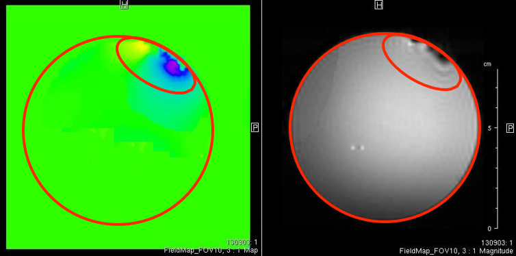
Ferrous headstage/electrodes [courtesy Leopold Lab] 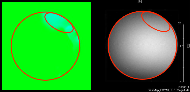
Non-ferrous headstage/electrodes [courtesy Leopold Lab]
Scanner Artifacts in Neural Recording
The next step is to verify the integrity of the neural recordings, both before and during the scan. The scanner artifact can be >100 mV on the recording signal. MRI artifact is not correlated with the field size. The bore diameter will have a bigger effect.
To do this:
-
Perform test recordings with the 50 kOhm resistor block in the fMRI kit. This tests the integrity of the headstage / amplifier recording as a baseline.
-
Run the system without a scan to observe the baseline noise.
-
Run the system with a scan to view the scanner artifact on the neural recording. Look for any saturation, and use the MRI Recording Processor gizmo interface to remove the scanner artifact.
-
View the scan to determine if there are any image artifacts.
Repeat the above tests in steps 2-4 with your electrode using an agar gel or saline brain phantom for a complete system test, from electrode to amplifier.
Important
With electrode in subject, check the neural recording data quality on the table top before moving it into the magnet. If there are issues, perform a standard saline test outside of the magnet as well.