Getting Started
Hardware Requirements
One of the challenges of recording electrophysiology during fMRI is the large artifact introduced by the scanner during imaging. The scanner artifact can be >100 mV on the recording signal, so you need a headstage and amplifier that won't saturate (clip) during the scan.
Headstages and Electrodes
Only non-ferrous headstages (passive or active) and electrodes should be used in the fMRI to avoid image distortion. See Minimizing Imaging Artifacts for an example of the image distortion.
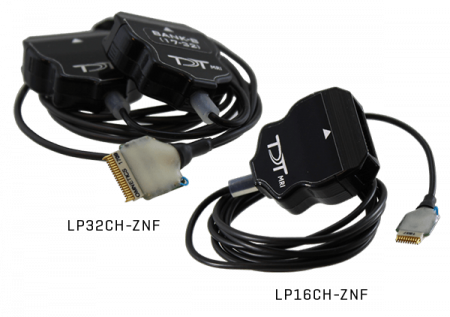
TDT non-ferrous headstages are available in 16-channel (LP16CH-ZNF) and 32-channel (LP32CH-ZNF) form factors, with standard 2 m cable. These headstages have a ±2.5 V input range, unity gain, and no filters.
For single unit / LFP recording, only fMRI-compatible probes can be used, with sites made of Platinum-Iridium (PtIr) or other materials. For EEG / EMG use non-ferrous materials that are also generally biocompatible. Some suggestions for material might be titanium (perhaps good for skull screws), Ag/AgCl, or gold. Make sure you also have non-ferrous wiring going out of the electrodes to whatever downstream headstage or connector you are using. Copper, gold, or platinum wires could work. Gold and platinum might be expensive though, and copper wire may heat up some during the scan.
Amplifier
Both the PZ5 analog amplifier and PZA Subject Interface (SI) analog amplifiers have a large enough input range (±500 mV) that they can handle artifacts from the scanner without saturating. They also have a large 124 dB dynamic range (least significant signal ~100 nV) to precisely capture the electrophysiology signal and can be DC-coupled to minimize signal distortion.
These are the only amplifiers that should be used with fMRI. Other amplifiers, including the digital headstages, have a much smaller input range and built-in filters. High-pass filters cause temporal shifts that make it more difficult for artifact removal. Low-pass filters cause ringing after the scan which increases the amount of signal lost immediately after the scan.
MRI Kit
TDT provides two cable kits for MRI compatible connections between the subject electrode interface and the amplifier, one for 16 channel headstage connections and one for 32 channel configurations.
The standard non-ferrous headstage cable is two meters. The MRI kit includes a two meter extension cable, so the distance between the amplifier and subject can be extended to four meters. This overall length is typically sufficient, but if more length is required then additional one meter extender cables are available. This length is measured from the center of the bore to the waveguide / filter plate interface between the MRI room and the control room.
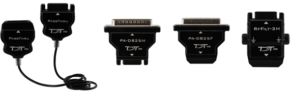
The MRI-NRKIT-16, 16 channel kit includes:
- (1) PassThru, passive extender cable, two meter length
- (1) PA-DB25F, DB26 male to DB25 female connector
- (1) PA-DB25M, DB26 female to DB25 male connector
- (1) RFFILT-3M, RF filter with 50 MHz low pass
The MRI-NRKIT-32, 32 channel kit includes:
- (2) PassThru
- (2) PA-DB25F
- (2) PA-DB25M
- (2) RFFILT-3M
See Penetration Panel for a discussion on the RF filter.
Each kit includes a 50 kOhm resistor test block for your headstage type (16-channel or 32-channel Omnetics).
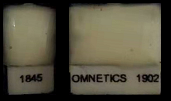 |
| MRI test resistor blocks |
Omnetics-Omnetics connectors (pin savers, gender change, or angled connectors) for connecting in tight spaces are available on request.
RZ Processor
The PZ5 and PZA Subject Interface connect to an RZ Processor. This handles the real-time signal processing, and communicates with the PC through an interface card.
Interface Card
The RZ Processor connects to the PC through either a PO5e or UZ3 PC interface.
Hardware and Software Setup
Carefully unbox your equipment and install the PO5e or UZ3 according to the System 3 Installation Guide. If you have a TDT WS4 or WS8 workstation, then a PO5e card will already be installed. Briefly - power down your computer* and place the PO5e card into an available PCIe slot in your computer. Next, install your TDT drivers and Synapse software from the USB Storage Drive that was provided with your shipment.
Note
*TDT drivers only function on Windows machines. Synapse will not run on Mac or Linux.
Below is a list of helpful online TDT resources with which users should be familiar before starting:
Synapse Training Videos
Narrated walkthroughs of the Synapse software. These are very helpful for beginner users first learning the Synapse environment.

Lightning Videos
Short, unnarrated videos that demonstrate specific actions in TDT software. These are referenced several times throughout this document, so look out for the blue icon
Knowledge Hub
Contains documentation for all TDT hardware and software. This is a great first resource for troubleshooting
Tech Notes
Contain information about known hardware or software issues and associated solutions or workarounds
Support Help
TDT Tech Support offers phone and remote screen sharing support via GoToAssist to customers M - F, 8 AM - 5 PM Eastern Time. For remote screen sharing assistance, please email support@tdt.com to schedule an appointment.
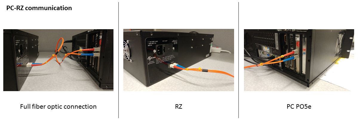
Establishing RZ processor and PC communication
Once the PO5e card is seated and TDT drivers and software are installed, you are ready to connect the RZ processor and PC together. The orange fiber optic cables* will be used for PC-RZ communication (see Sys III manual for more details). Please connect the fiber optics to the correct ports on the RZ and PO5e card, as shown in the diagram below (red optical connector to 'Out' or Red-labelled ports on RZ and PC).
Note
*Your fiber optic cable may be a different length.
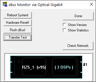 |
| zBusMon with RZ5D Processor |
Next, turn the RZ on. The display screen on the processor should illuminate with information about the unit's DSP cards. To check whether there is communication between the RZ and the PC, open the zBusMon application (shown to the right). The RZ processor should appear with information about the driver version and number of DSP cards. Click Transfer Test to test communication.
If you get an error upon performing an initial transfer test, try performing a 'Reboot System!' first. If there is a consistent error in zBusMon, or you do not see your RZ appear, please contact TDT for assistance.
Connect your amplifier
- If using a PZ5 and RZ2 processor, connect the PZ5 to the port labeled PZ Amplifier on the back of the RZ2.
- If using a PZ5 and a different processor, connect it to the port labeled To PZ. On an RZ5D, this might be on the front panel. Otherwise it will be on the back of the RZ.
- If using a PZA Subject Interface, connect it to the optic port labeled To SI. On an RZ5D, this might be on the front panel. Otherwise it will be on the back of the RZ.
Important
The PZ5 and PZA Subject Interface are battery power and optically isolated. Make sure that the charger cable is disconnected from the amplifier and the wall sock while recording.
Launching Synapse
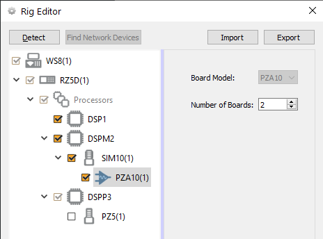
With your RZ and amplifier on and connected, launch Synapse. If this is your first time launching Synapse, the Rig Editor will appear and it will be blank. Click Detect for Synapse to recognize your RZ and the number of cards installed in your PZ5 or PZA Subject Interface, and their type.
Note
PZ5 card detection is available in v96 Synapse and later only.
In this example, a PZA Subject Interface is connected to an RZ5D. A PC, RZ5D, three DSPs, the Subject Interface (SIM10), and an unchecked PZ5 in the tree. Finally, click Ok to exit the Rig Editor.
Note
The PZ5 is unchecked because there isn't one connected.
The Rig Editor can be accessed later for modification through the Synapse Menu if your hardware changes.
Amplifier Setup
Software Configuration
In Synapse, in the PZ5 or PZA Subject Interface options set the subamplifier to 'DC Coupled' mode. Using DC coupling increases the probability that the artifact removal will be successful and avoids additional signal distortion caused by AC coupling.
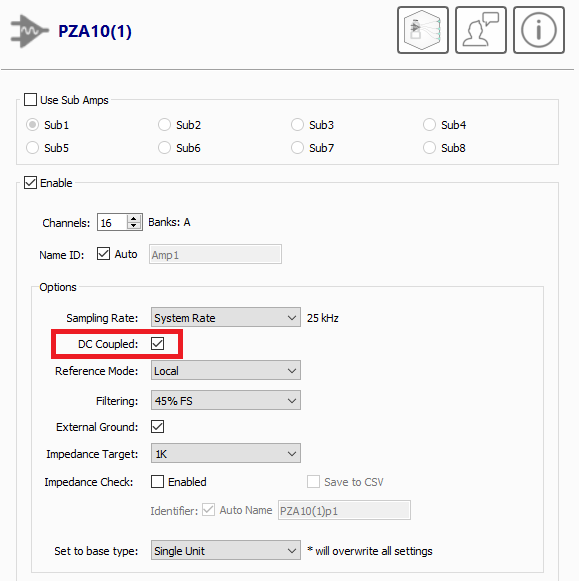 |
| PZA configuration options |
The External Ground option connects the subamplifier / subject ground to the banana jack on the back of the PZ5 / PZA Subject Interface. Note that the subject ground should never be connected to the MRI ground. See Penetration Panel for more information on system grounding.
Touchscreen Configuration
The amplifier produces high frequency EMF that is outside of any electrophysiological signal range, but is in the frequency range used by the scanner. This can introduce noise artifacts in the scanner image, as shown in the example below. These artifact show up as faint white lines across the image.
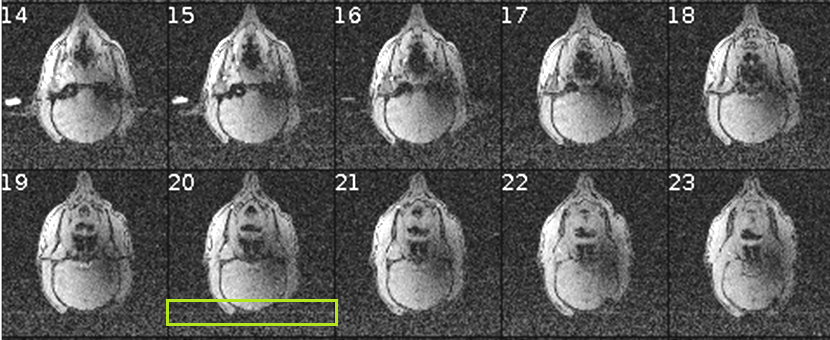 |
| Example amplifier artifact in scanner image |
Two of the built-in features of the PZ5 / PZA Subject Interface introduce artifact and must be disabled during recording.
-
Turn off amplifier wifi
Older amplifiers have built-in wifi to allow network updates. This must be disabled during the scan (and can remain permanently disabled, use the Ethernet port to do network updates).
-
PZ5: Press the 'PZ5' icon on the touchscreen -> Config -> More -> set Wireless to 'Off'
-
PZA Subject Interface: Press the 'SIM' icon on the touchscreen -> Config -> set Wireless to 'Off'
-
-
Turn off amplifier touchscreen
The touchscreen is a big source of high frequency EMF. During the actual scan, the touchscreen must be turned off.
-
PZ5: Press the 'PZ5' icon on the touchscreen -> Config -> set 'Autosleep' to '5 min'. This is currently the minimum setting and will turn off the touchscreen display after 5 minutes of inactivity.
To immediately turn off the PZ5 screen, make sure you are on the main screen and swipe three fingers across the screen in any direction.

-
PZA Subject Interface: Press the brightness icon on the touchscreen, this turns off the touchscreen display after 5 seconds.
-