Configuration
Prior to presenting a stimulus signal and acquiring response data, stimulus and data acquisition parameters must be configured. These parameters are saved as part of the BioSigRZ configuration file. The information in this section can be used to modify an existing configuration or to create a new configuration file.
Open existing BioSigRZ configuration files and save new ones from the File menu.
Creating Configurations
When creating a new configuration file, it is necessary to complete the steps below prior to presenting a stimulus signal and acquiring response data.
-
Define stimulus signal parameters
-
Define data acquisition parameters
Optionally the user might also wish to:
-
Review the calibration
-
Specify the stimulus schedule
-
Modify the Target Device setup
Defining Stimulus Parameters
Stimulus parameters are defined from the Stimulus Setup dialog box.
To access the Stimulus Setup dialog box:
-
Select Stimulus from the Setup menu or click the Setup Stimulus
 button.
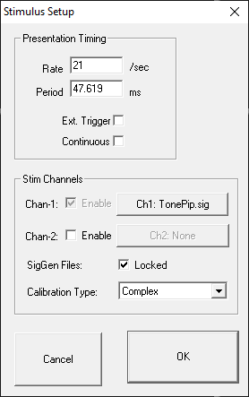
Defining the Stimulus
You may define a stimulus on one or two channels. Set the SIG file and calibration file for each channel by clicking the button for that channel. There is more information on that in the following sections.
Calibration Type
BiosigRZ takes the speaker calibration curve (*.TCF file) and generates an FIR filter to flatten the response. When the Calibration Type is set to Complex, all signals are passed through this filter before they are sent out the DACs/speakers.
In some instances, if the speaker response curve has large variance with sharp notches/peaks (this usually happens with closed-field speakers at higher frequencies), the FIR filter doesn't perfectly represent this and can affect the output signal quality, particularly for tone pip stimuli. In this case, set the Calibration Type to 'Tonal' and BioSigRZ will use a lookup table to scale the signal based on the primary frequency, instead of using the FIR filter.
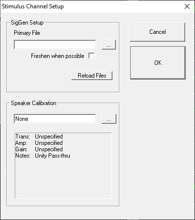
Specifying the SigGenRZ File
BioSigRZ generates a stimulus signal based on signal parameters read from previously defined SigGenRZ signal files (*.sig files). To define a stimulus signal, the user specifies the desired *.sig file.
To specify the stimulus file:
-
Click the Browse
 button to the right of
the Primary File field.
button to the right of
the Primary File field. -
Select the desired file.
or
- Type in the desired file name in the Primary File field.
Stimulus Refresh
BioSigRZ generates a stimulus signal based on the parameters specified in the SigGenRZ file. The generated signal is stored in a buffer. This buffered signal is then presented as a stimulus. A stimulus refresh occurs whenever the signal currently stored in the buffer is replaced with a freshly generated stimulus signal.
In theory, a stimulus signal could be refreshed: (1) prior to each presentation or (2) prior to a new set of stimulus variable conditions, called a SigGen Index or SGI.
In practice, however, the ability to perform a stimulus refresh is limited by processing considerations. The real time processing of incoming response data must take precedence over the refresh of the stimulus signal. BioSigRZ performs a stimulus refresh as follows:
-
The stimulus signal is always refreshed prior to a new SGI.
This automatic refresh is necessary in order to reflect any changes in stimulus signal parameter values associated with the new SGI.
-
The stimulus signal may be refreshed when possible within an SGI. This option is enabled by checking the Freshen when possible checkbox.
Refreshing Non-Noise Stimuli
Within an SGI, non-noise stimulus signals, such as clicks and periodic waveforms, remain constant. These signals need only be refreshed prior to a new SGI. For these signals, do not check Freshen when possible.
Refreshing Noise Stimuli
It may be desirable to refresh noise stimuli. While BioSigRZ cannot guarantee that a noise signal will be refreshed for every presentation within an SGI, it will attempt to refresh the signal when possible. If the Freshen when possible option is chosen, the noise stimulus will be refreshed whenever there are no processing demands being made by incoming data. If you wish the noise stimulus to remain constant throughout all presentations in a given SGI, do not specify Freshen when possible.
To refresh the stimulus whenever possible:
- Check the Freshen when possible check box
Locking SigGen Files
You may modify SigGenRZ variables from within BioSigRZ.
If the Lock SigGen Files checkbox is enabled, changes you make to the SigGenRZ variables within BioSigRZ will be saved with the *.acf file. Any changes to the *.sig file that are done outside of BioSigRZ will have no effect on the configuration, because BioSigRZ has 'locked' a copy of the SigGen file inside of the *.acf file.
If the Lock SigGen Files checkbox is unchecked, the SigGen file is reloaded from disk every time you open the *.acf file and your changes to the variables within BioSigRZ will be overwritten and lost.
To lock a SigGen File for the current *.acf:
- Check the Lock SigGen Files check box
Reloading the SigGenRZ Stimulus File
SigGenRZ files are automatically loaded:
-
When the file name is specified (see below).
-
When an existing BioSigRZ configuration file (*.acf file) is loaded.
SigGenRZ files may also be manually loaded by:
- Browsing to the desired SigGenRZ file.
Included in the SigGenRZ file is information defining how variables will change as a function of the SGI. Once a SigGenRZ file has been loaded, this information is available to the BioSigRZ application and will be saved in the BioSigRZ configuration file (*.acf file).
In some cases, it may be necessary to modify these stimulus variables. BioSigRZ allows you to make local changes to stimulus variables for Channel 1, only. (Note that with a two channel system, both SigGenRZ files should have the same variables. BioSigRZ only implements variables in the file for Channel 1.)
Reload File
When you reload a SigGenRZ file with variables, the variable schedule currently defined in BioSigRZ will be replaced with the schedule stored in the SigGenRZ file.
To reload a SigGenRZ file:
- Click the Reload File button.
Presentation Timing
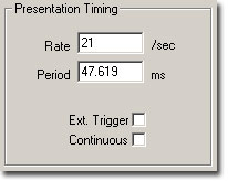
Temporal parameters associated with the presentation of the stimulus signal are defined in the Presentation Timing section of the Setup Stimulus dialog box.
The Presentation parameters consist of the following:
-
Presentation Rate (stimuli/second)
-
Presentation Period (milliseconds) = 1000/Presentation Rate (sec)
-
Ext. Trigger - Not supported at this time
-
Continuous - Enable/disable continuous presentation.
Presentation Rate
You may define the Presentation Rate by entering a value in the Presentation Rate field. When you leave this field, the value of the Presentation Period field will be calculated automatically.
Presentation Period
You may define the Presentation Period by entering a value in the Presentation Period field. When you leave this field, the value of the Presentation Rate field will be calculated automatically.
When Continuous is enabled (see below), the presentation period is automatically defined as the length of the SigGenRZ signal assigned to stimulus channel 1. When continuous is enabled, you may not edit the Presentation Rate or Presentation Period.
Note
When Continuous is not enabled, the Presentation Period must be 1.25 times longer than the stimulus and acquisition duration.
Ext. Trigger
This feature is not currently supported at this time.
Continuous
When Continuous is checked, the stimulus will be played continuously. Upon reaching the end of the signal, BioSigRZ will loop back to the beginning of the buffer and replay the signal. This cycle will continue throughout continuous signal play.
Note
When selecting continuous record the assigned SigGenRZ file must be designed for continuous stimulus presentation.
Speaker Calibration
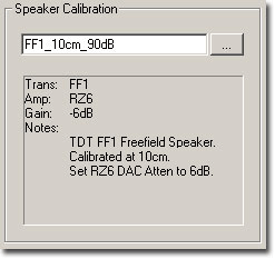
Calibration associated with the presentation of the stimulus signal can be loaded in the Speaker Calibration section of the Setup Stimulus dialog box.
To load a Calibration file:
-
Click the Browse
button. -
Select the desired file or type in the desired file name in the text field.
A text area displays specific information regarding the currently selected calibration file including the transducer, amplifier, gain setting, and any additional notes.
The Gain value tells you what value to set the manual attenuator on the RZ6. For example, a gain value of -6 dB indicates that this calibration file was created with the manual attenuator knob set to 6 dB, so in order for this calibration to be accurate you must set the manual attenuator knob to 6 dB.
Note
Calibration files are provided for common speakers and use the extension .tcf.
Defining Data Acquisition Parameters
Data Acquisition parameters are defined from the Acquisition Setup dialog box.
To access the Acquisition Setup dialog box:
-
Select Acquisition from the Setup menu or click the Setup Acquisition
 button.
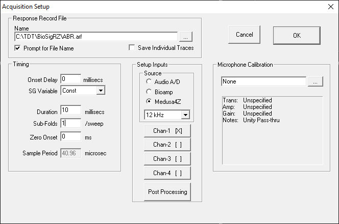
Response Record File
Response record files, or history record files, (.arf) are continuously maintained during data acquisition. Each averaged record is appended to the history record file.
Name
This will be the default history record file name.
Prompt for File Name
When this box is checked, BioSigRZ will always prompt you for a file name before stimulus presentation begins, allowing the option to specify separate *.arf files.
Save Individual Traces
When this box is checked, a CSV file containing all individual trace data is saved next to the ARF file for each average saved into the ARF file. The file name format is {ARFNAME}-{GROUP}-{SGI}-{CHANNEL}-{NREPEAT}.csv
Within the CSV file the first row is headers for group, sgi, channel, subject, ref1, ref2, memo, and all variable names. The second row is the values for those headers. Each row after that contains an individual sweep.
During averaging, BioSigRZ requires two additional sweep triggers to move the internal buffer on the RZ6 to get it ready to read. Because of this, there will be two more traces at the end of this file than the specified number of desired averages.
The CSV files that are produced will be large (typically 14-15 MB per SGI) but because they are text files they compress well and typically take up 4-5 MB when zipped.
Individual Traces and the Acquisition Channel Setup dialog settings
The Gain setting in the Acquisition Channel Setup dialog is already divided out of this data.
The DC component is not removed from these traces, even if "AC Couple" is selected in the "Preprocessing" settings of the Acquisition Channel Setup dialog (which is the default).
Any "Post Processing" is also not applied, which means the DPOAE individual traces will be the time domain signals.
Timing
Onset Delay
The value in the Onset Delay field defines the time delay in milliseconds from the time of stimulus onset to the beginning of response signal acquisition. This field is set to zero and disabled when continuous signal presentation is enabled.
SG Variable
Onset delay may be defined as a constant or as a SigGenRZ variable. This box is disabled when continuous signal presentation is enabled.
Duration
The value in the Duration field specifies the length in milliseconds of the acquired response signal. When continuous signal presentation is enabled, this value will default to the duration of the SigGenRZ signal and the field will be disabled.
Sub-Folds
You may divide the acquired signal into subunits that are folded onto each other. These sub-folds are added to one another. The resulting composite signal is averaged. For example, if an acquired signal of 50 milliseconds is assigned 2 sub-folds, the result is two 25 millisecond sub-folds. The first 25 millisecond sub-fold will be added to the second 25 millisecond sub-fold. Sub-folds may be used with both non-continuous and continuous signals.
Zero Onset
Zero Onset defines a duration beginning at 0 milliseconds during which the acquired signal will be set to zero. For example, if Zero Onset is defined as 20 milliseconds, the first 20 milliseconds of the acquired signal will be set to zero.
Sample Period
This field displays the current sample period in microseconds associated with the acquisition sampling rate (this rate is defined in the assigned .sig file and cannot be edited).
Setup Inputs
Select an input source (the RZ6 device analog A/D, RA4PA Bioamp, or Medusa4Z). If choosing Medusa4Z, also set the sample rate of the Medusa4Z device. Next, define configuration parameters for the acquisition channel.
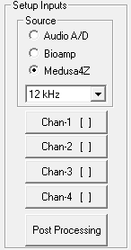
To setup an acquisition channel:
-
Click the desired acquisition channel button. The Acquisition Channel Setup dialog box opens.
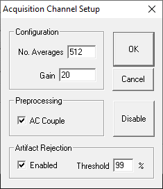
Configuration
No. Averages
The value of Number Averages determines the number of response signals acquired and averaged for every SGI. Number Averages must be at least 1 and cannot exceed 3000.
Gain
The value specified in the Gain field is used to adjust the voltage of the acquired data signal. Enter the gain applied by the preamplifier you are using. The TDT RA4LI applies 20X gain. The Medusa4Z gain is 1X. If using the A/D inputs you may have a different gain setting.
Preprocessing
AC Couple: Checking this box enables AC Coupling. AC Coupling removes the DC component by subtracting the signal average.
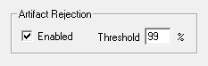
Artifact Rejection
In some cases, anomalous amplitude values may indicate an artifact in the acquired data signal. BioSigRZ provides a means for detecting and rejecting signals with such artifacts, Artifact Rejection. By enabling Artifact Rejection, you can specify at which peak amplitude you wish to reject an acquired signal. This amplitude is specified as a percentage of the threshold relative to the maximum voltage input (±10 Volts or input signal).
Note
Signals rejected through Artifact Rejection are not included in the average for each SGI.
To enable Artifact Rejection:
-
Check Enabled in the Artifact Rejection area
-
Enter the desired percentage in the Threshold field
or
-
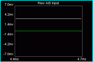
Select the Raw A/D Input in the Multi-Purpose Plot.
-
Place the mouse pointer in the plot.
-
Hold down the left mouse button and the Ctrl key. A threshold line appears.
-
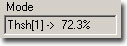
Drag until the desired artifact rejection is reached. The threshold percentage will be displayed in the Mode field.
Enabling/Disabling a Channel
Acquisition Channel 1 is always enabled. Channel 2 is disabled by default and is not supported by BioSigRZ at this time. However, if the system has been modified to use two channels, Channel 2 can be enabled or disabled. Contact TDT for more information if two channels are required.
Important
Enabling channel 2 in BioSigRZ will not enable acquisition on a second channel unless the circuit file has been modified. Contact TDT for assistance.
For systems running custom circuit files:
To enable Acquisition channel 2:
-
Click the Chan-2 [ ] button
-
Click OK
To disable Acquisition channel 2:
-
Click the Chan-2 [X] button
-
Click Disable
Once you have enabled or disabled a channel, you will be returned to the Acquisition Setup screen. By examining the Edit Acquisition Channels buttons, you can quickly determine which channels are enabled. Enable channels display [X] on their buttons.
Post Processing
You may apply various types of post-processing to the acquired signal.
To apply post processing:
-
Click the Post Processing button.
You will see the Post Processing dialog box. From this box you may enable a variety of post processing options.

Hanning Window
Applies a Hanning window to the acquired signal.
Truncate to Rad-2
Truncates the number of data points to radix 2.
Mag Spectrum (dB)
Displays intensity in the logarithmic units of decibels. Uses an N-point FFT where N is half of the acquisition window. The default DPOAE acquisition window is 4096 samples, so the default FFT is 2048 points.
Phase Spectrum (rads)
Displays the phase spectrum in radians.
Reviewing Calibration
In most cases calibration is not required; however, calibration can be reviewed using the calibration dialog.
To view the current calibration:
-
Select Calibration from the Setup menu or click the Calibration
 button.
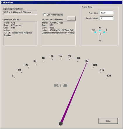
SigGen Specifications
Specifies the calibration defined in the currently loaded .sig file.
Speaker Calibration
Lists the details of the currently configured calibration file (.tcf) loaded in the Stimulus Setup dialog. See Defining Stimulus Parameters. for more information.
Use Acquire Spec
When checked, the details of the calibration file (.tcf) currently specified in the Acquisition Setup dialog will be displayed in the Microphone Calibration text area below. If unchecked you may specify a different microphone calibration file to be used with the Probe Tone test. This does not change the Acquisition Setup for your experiment configuration.
Microphone Calibration
Lists the details of the currently configured calibration file (.tcf) loaded in the Acquisition Setup dialog. See Defining Data Acquisition Parameters for more information.
Probe Tone
Present a probe tone to test connected equipment.
Freq (Hz): Specify the frequency for the probe tone.
Level (vrms): Specify the level of the probe tone. Typically 1 V is used (all examples are calibrated to 1 Vrms = 90 dB).
Probe Tone Dial
Click and drag to the desired output channel to enable the probe tone presentation. The large dial at the bottom of the dialog will display the measured sound level in dB SPL recorded by the microphone.
Specifying the Stimulus Schedule
When the stimulus is defined, either by loading a standard configuration file or by specifying a stimulus file in the Stimulus Setup dialog, a complete list of signal parameters and variables are added to the BioSigRZ file. During stimulus presentation, the values of the variables change as a function of the SGI (a set of variable conditions). This is called the stimulus schedule. Both the stimulus schedule and the variable definitions can be modified in BioSigRZ.
Viewing the Current Stimulus Schedule
To view the current stimulus schedule:
-
Select Modify Schedule from the Operations menu. In addition, you can also select SigGen Variables from the Setup menu or click the Modify SigGen Variables
 button. This prompts the SigGen
Variable Control dialog.
button. This prompts the SigGen
Variable Control dialog.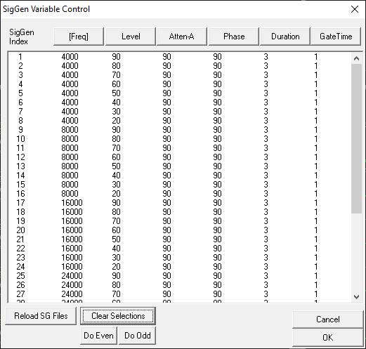
The SigGenRZ Variable Control dialog box displays the current stimulus schedule. Variable values are shown for each SGI.
You may scroll through the stimulus schedule as follows:
To scroll up and down
- Use the Vertical Scroll Bar
Once you have viewed the stimulus schedule, you may:
-
Accept the current stimulus schedule
-
Modify the current stimulus schedule
-
Modify variables
To accept the current stimulus schedule:
- Click OK
Modifying the Stimulus Schedule
You may wish to present a subset of the current stimulus schedule. To do so, just select the SGIs to be included in the subset for presentation. When no SGIs are selected, BioSigRZ will present the entire stimulus schedule. Otherwise, BioSigRZ will present only the selected SGIs.
To select a single SGI:
- Click the desired SGI
To select multiple, non-contiguous SGIs:
- Ctrl+Click the desired SGIs
To select a group of contiguous SGIs:
-
Place the mouse pointer over the first SGI
-
Hold down the left mouse button
-
Drag the mouse pointer to the last SGI
-
Release the left mouse button
or
-
Click the first SGI
-
Shift+Click the last SGI.
To select all odd SGIs:
- Click the Do Odd button
To select all even SGIs:
- Click the Do Even button
To deselect a single SGI:
- Ctrl+Click the desired SGI
To deselect all SGIs:
- Click the Clear Selections button
Modifying Variables
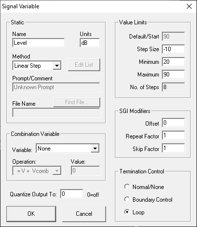
Variables change the signal parameters as a function of the SigGen Index (SGI) and are defined within SigGenRZ and can be modified in BioSigRZ through the use of the Signal Variable dialog.
Note
When using dual channel stimuli such as in the standard DPOAE configuration, changes to signal variables will affect channels 1and 2. Variables may also be altered in SigGenRZ.
To access the Signal Variable dialog box:
- Click the name of the variable you wish to change in the SigGen Variable dialog.
The Signal Variable dialog box available in BioSigRZ is much the same as the dialog used to define variable in SigGenRZ. This section provides information about the settings most pertinent to modifying variables from within SigGenRZ. For more information on all settings, see the SigGenRZ Manual.
Name and Units
In general, the variable name and units should not be changed in BioSigRZ.
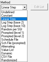
Commonly used Variable Methods
Method defines the mechanism (function) of altering variable values as a function of the SigGen Index (SGI).
See the SigGenRZ Manual for more information on the available variable methods.
Some of the more commonly used Variable methods include:
Constant
This method sets the variable equal to a constant value. This method is most useful when more than one parameter will be set to the same value. Constant defines a variable that will always have the same value as given in the Default/Start field of the Value Limits box. This value will be a floating-point constant between 1.2E-38 to 3.4E+38.
Linear Step
For each SigGen Index (SGI) increment, Linear Step defines a variable that will increment by the Step value specified in the Value Limits box.
Alternating
The value of the variable alternates between the values defined in the Minimum and Maximum fields. The variable value does not depend on SGI value, but on the number of the continuous presentation of the current signal interval. In the Variables group box, an alternating variable must be defined next to another predefined variable, or as the first variable.
Value List
Variable values are specified in SigGenRZ during the signal design process. A maximum of 80 variable values can be specified for the variable.
To enter or modify a variable list:
-
Select Value List from the Method drop-down box
-
Click the Edit List button
-
Enter values to define the variable.
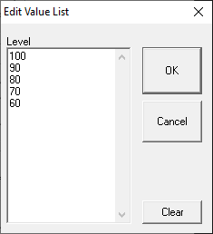
-
Click OK
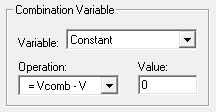
Combination Variables
In some cases, a simple variable is not sufficient to define a signal. A combination variable is a variable whose value is calculated by performing a mathematical operation on another variable or a constant.
To Define a Combination Variable:
-
Open the Signal Variable dialog, either by selecting SigGen Variables from the Setup menu, or by clicking the SigGen Variables
button. -
Name and define the combination variable in the General box
-
In the Combination Variable box select an Operation to apply to this variable (V in the Operation formula). Combination variables can be defined using addition, subtraction, multiplication, and division.
Operation:
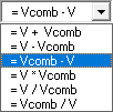
The Variable drop down menu in the Combination Variable box is used to define
Vcomb in the operation. Vcomb can be defined as either a constant, and its
value entered in the Value box, or it can be defined as another variable.
When the stimulus signals that contain combination variables are used in BioSigRZ, the combination variable value is calculated and used in generating the signal and controlling the peripherals.
Value Limits
From the Value Limits group box you can define the manner in which a variable value changes as a function of the SigGen Index (SGI) value. You can also define the range of allowable values for the variable. For combination variables, these values will only apply to primary variable(s), and will not limit the combination variable result. However, a zero will be used when the combination variable result becomes a divide-by-zero.
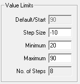
Default/Start
Default/Start defines the value of the variable when the SigGen Index = 1. This is also the value for a constant variable. When prompt variables (Prompt Level 1, Prompt Level 2, Prompted File) and Dynamic variables are defined, this value is also the default variable value before the value is specified.
Step Size
Step determines how much the variable will be systematically varied as a function of the SigGen Index value. A zero Step Size for other functions will define a constant variable (except when the method is Randomized).
Minimum
In the Minimum field, you define the minimum allowable value for the variable.
Maximum
In the Maximum field, you define the maximum value allowed for the variable.
Note
Minimum value must be smaller than Maximum, and Default/Start must be within Minimum and Maximum range.
No. of Steps
This field displays the total number of steps between the minimum and maximum variable values, when appropriate. This field is not editable.
SGI Modifiers
SigGen Index (SGI) is a unique number which starts at 1 and increments by 1 when an interval is presented. This SGI applies to every variable by means of SGI Modifiers. These SGI Modifiers become important when SigGenRZ is used to design signals with complicated variables or nested variables.
By default, a stimulus presentation begins with the SGI = 1. Often, the stimulus signal generated at SGI = 1 is presented until a desired number of response signals have been attained. The SGI is incremented by 1 then all variables and the entire signal are updated. This process continues until all SGIs have been presented.Through use of SGI Modifiers, it is possible to customize the process of SGI incrementation for individual variables. You may:
-
Start variable calculation with an offset to SGI
-
Repeat SGI
-
Skip a specified number of SGIs
-
Create nested variables
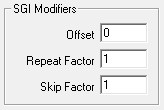
Offset
The initial SGI is always 1. When SGI is used to calculate variables, any deviations from this default value are termed offsets. If you wish to start stimulus presentation with a variable calculated based on a modified SGI = n, then enter n in the Offset field. If the variable's values are 0, 1, 2, 3, 4, 5, ..., corresponding to SGI = 0, 1, 2, 3, 4, 5, ..., an Offset = 2 will result in modified SGI = 2, 3, 4, 5, 6, ..., and so the variable's values 2, 3, 4, 5, 6, ..., correspond to SGI = 0, 1, 2, 3, 4, 5, ....
The default value of Offset is 0, that is, the modified SGI equals to SGI. The value of Offset must be no less than 10,000 and no greater than 10,000.
Repeat Factor
The Repeat Factor field specifies the number of times, r, an SGI will be used as modified SGI. For example, when r = 2, modified SGI will be 1, 1, 2, 2, 3, 3, ..., corresponding to SGI = 1, 2, 3, 4, 5, 6, ....
By default, Repeat Factor is set to 1 (use each SGI once). Repeat Factor may be no less than 1 and no greater than 100.
By using a Repeat Factor in tandem with a Termination Control specification of Loop (see next section), you can create nested variables.
Skip Factor
The Skip Factor field specifies the number of the SGIs is to be ignored in the modified SGI. For example, if Skip Factor is 2, modified SGI will be 1, 3, 5, 7, 9, ..., corresponding to SGI= 1, 2, 3, 4, 5, 6, ....
By default, Skip Factor is set to 1. Skip factor may be no less than 1 and no greater than 100.
Termination Control
You can control the termination of the SGI by choosing one of three types of termination control.
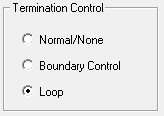
Normal/None
When Normal/None is chosen, the variable will not be considered in termination control. Thus, if a minimum or maximum variable value is reached, signal play will not terminate, nor will the variable value loop. The variable will instead remain at the minimum or maximum value. Continuous signal generation will be based on the final variable value. In this case, signal play will be terminated by other variables or manually.
Boundary Control
Boundary Control provides a method of experiment termination. When Boundary Control is chosen, the SigGen Index (SGI) will not be incremented if such an action would cause the value of the variable to be:
-
Less than the Minimum value
-
Greater than the Maximum value
Such failure to increment the SGI produces differing results, depending on the application.
When a boundary is reached and the SGI ceases to be incremented, signal generation will continue for the current SGI, but no more response data will be collected.
Note
Specification of Minimum and Maximum does not provide boundary control. Minimum and Maximum simply define the limits of parameter variation. The variable will not be allowed to go beyond either of these limits.
Loop
When Loop is chosen, parameters continuously loop through the series of variable values as SGI increments.
See the SigGenRZ Manual for more information on the variable parameters contained in this dialog.
Modifying the Target Device Setup
BioSigRZ is designed to run exclusively with the RZ6 Multi I/O processor. A standard RPvdsEx circuit file running at ~200 kHz is implemented by default and is suitable for most users.
In those rare cases where a custom circuit file is required, the circuit file may be overridden in the Target Device Setup. Contact TDT for assistance if you wish to use custom circuit files.
To access the Setup Target Hardware dialog box:
-
Select Target Device from the File menu.
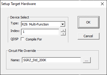
Device Select
Type
BioSigRZ supports the RZ6 only.
Index
If a system comprises more than one RZ6 the index number can be used to specify which RZ6 to use.
QDSP
This option can be ignored.
Circuit File Override
Name
If a custom circuit file (designed in RPvdsEx) is required. Type or browse to select the file name.