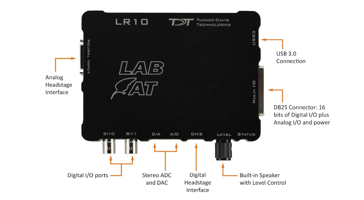
Lab Rat Hardware
Analog Headstage Interface
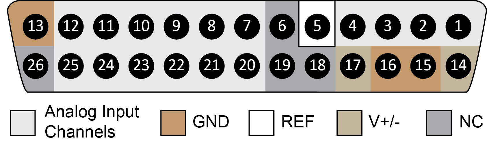
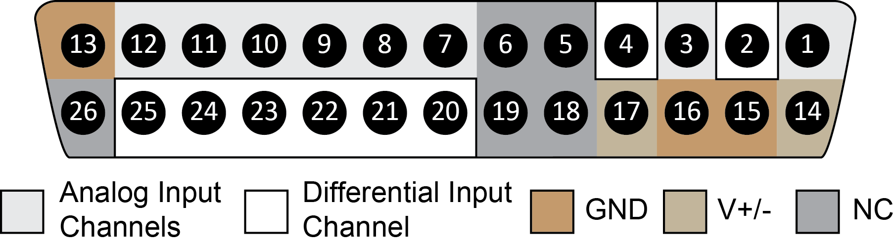
A DB26 connector for interfacing the AC16LR or the SB4 to the Lab Rat for up to 16 channels of neural signal acquisition.
DB26 Neural Input - Shared Reference Mode
DB26 Neural Input - Differential Mode
Note
There are 8 (+) channels and 8 (-) channels per DB26 connector.
Note
Contact TDT technical support (+1.386.462.9622 or support@tdt.com) before attempting to make any custom connections.
Digital Headstage Interface
A 12-pin Omnetics nano connector used for interfacing with an Intan-based digital headstage, such as TDT's ZD32 Digital ZIF-Clip® headstage. The interface supports up to 32 channels of digital data acquisition.
USB-C 3.0 Connector
A reversible USB connector for communication between the Lab Rat and a Windows-based computer. Use the provided C-to-A adapter if your computer/laptop doesn't have a C-style USB connector. The laptop or computer must support USB 3.0.
LR10 Technical Specifications
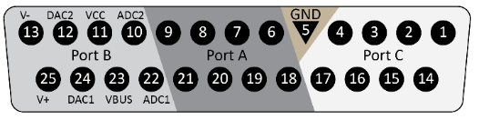
DB25 Multi I/O Port
This port provides access to 16 bits of digital I/O, two ±3 V analog inputs, two ±3 V analog outputs, and power. Pinouts are shown looking into the connector.
Bit 0 and Bit 1 BNC Ports
Bit0 and Bit1 on the Lab Rat interface module are BNC connections that map to Bits C0 and C1 on the Lab Rat. These connections are ideal for synchronizing the Lab Rat with BNC-based TTL triggers to and from external hardware. These can be configured in the Lab Rat object in Synapse Lite software. When performing TTL communications over BNC cables, be sure to use a shielded and as-short-as-possible cable for maximum signal integrity.
Stereo A/D and D/A Ports
Each of the ADC / DAC ports are ⅛" stereo jacks for two-channel analog signals for interacting with external hardware with up to ±3 V dynamic range. The speaker on the top of the Lab Rat is connected to the first D/A channel. The level knob on the Lab Rat interface module controls the speaker volume. The ADC input impedance is 200 kΩ.
Important
Do not exceed ±5 V on the ADC inputs
Status LED
The LED on the Lab Rat interface module indicates the run-time status of the device. Listed below are the various indicator states of the status LED:
Green LED
Solid - device is ready to run, system is idle.
Flashing - device is running and acquiring data.
Red LED
Flashing - device is running but there is a synchronization error with the computer. This happens if Corpus is not reading data fast enough, which means there is some other process on your computer that is consuming too many resources. There will also be a data acquisition error in Synapse Lite. If the error does not resolve itself, check for other running processes that might be interfering with Corpus and restart your recording in Synapse.
Power External Devices
You can use the VCC and VBUS pins on the Multi I/O Port to power external devices, such as sensors, relays, servos, and more. Be sure to check the specs of your external device and compare it to the allowed power draw listed in the LR10 DB25 Multi I/O Port pinout on the previous page.