Running a Calibration
Calibration Fundamentals
D/A Converters
It is important to understand how the D/A converter (DAC) on your real-time processor generates signals and how to best take advantage of the DAC for high signal quality. Different processor devices have different bit resolutions and different maximum voltage outputs.
We will discuss the RP2.1, RX6, and RZ6 here, because they are commonly used to generate stimulus signals.
The RP2.1, RX6, and RZ6
The RP2.1, RX6, and RZ6 DACs can generate a maximum signal of ±10 V peak-to-peak. This signal is generated digitally with 24-bits, meaning there are 2^24 discrete values that the DAC can generate to represent different voltages. This gives the DAC about a 144 dB theoretical dynamic range between the smallest and largest signal that can be produced. In practice, the signal to noise ratio on the RP2.1 is about 105 dB.
It is best to try to generate the largest signal possible out of the DAC. This will give you the best signal to noise ratio, and also lets you take advantage of the full dynamic range of the DAC.
Signal-to-Noise Ratio
All electrical systems have some level of noise in them. The noise coming out of the DAC is the same whether you are generating a 9 V or a 9 mV signal. Therefore, the signal to noise ratio of your signal will be higher the closer you get to the 10 V maximum of the DAC.
Clipping
If you try to generate a signal larger than 10 V, the DAC will clip the signal. That is, the peaks of the signal that exceed 10 V will be set to 10 V, and your signal will not be faithfully reproduced.
How Normalization Files Work
The purpose of normalization files is to flatten the frequency response of the speaker by adjusting the voltage of the digital signal that is played out of the D/A converter. In SigGenRP, the normalization curve is added to signals generated in the frequency domain to produce the normalized time signal, which is then played.
Since the dynamic range of the DAC is 144 dB, this is the theoretical maximum range that a normalization curve could have before there was clipping or no signal was produced by the DAC. However, if you normalize down 90 dB, that only gives you 54 dB worth of dynamic range. A tone could then only be made with a handful of discrete values, and its quality would be diminished. Thus, it is best to normalize over a smaller range of the DAC, around 30 dB. SigCalRP has built in warnings for indicating that a signal will clip or be too small.
Using a PA5 Programmable Attenuator to Calibrate a Tone Series
If your SigGenRP signal consists of a single tone where the frequency may vary over separate SGI's, then you could use a PA5 to calibrate your signals instead of a normalization file.
The advantages of using a PA5 for calibration include:
- You can use either the Time or Frequency methods of signal generation in SigGen.
- The signal-to-noise ratio of all of the frequencies tested will be the same.
- You can play a large signal out of the DAC and use the wide dynamic range of the PA5 to calibrate the signal over a larger range.
SigCalRP will generate a Variable Schedule File containing values that should be sent to the PA5 at each frequency to calibrate the signals.
Configuring Signals and Acquisition
Signal Setup
Open the Signal Setup dialog from the Setup menu to configure the range of frequencies that will be tested. The default test level is 9 V to maximize the dynamic range of the DAC. Set the start and stop frequencies to cover the entire range that you will want to use. Use a large step value for a quick first run to see how flat the speaker is over that frequency range. This can later be set to a smaller value to produce the normalization file.
Acquisition Setup
For the initial run, use the default settings in the Acquisition Setup dialog. This will allow you to quickly estimate how flat the speaker is. For the final run, you can increase the number of averages and FFT length to get a more precise calibration.
Enter the microphone calibration for your microphone and amplifier. It is important that you have a microphone with a known calibration. The accuracy of the calibration depends on the accuracy of the microphone.
Hardware Configuration
The figure below shows a typical hardware setup using an RP2 to perform the calibration of a speaker. Other hardware setups are possible.
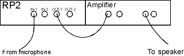
There are generally two signal paths:
- Signal Presentation: This is the path from the processor device Output to the speaker or other transducer. There may be other modules in this path, such as an HB7 Headphone Buffer or SA1 Speaker Amplifier.
- Signal Acquisition: This is the path from the microphone (or other measurement device) to the processor device Input. There may be other modules in this path, such as the MA3 microphone amplifier.
Running the Calibration
Once the signal and acquisition are configured, make sure the TDT hardware is configured as you will use it in your experiment. Connect the DAC to the amplifier and speaker that will be used in your experiment. Connect the microphone to the microphone amplifier and then to channel 1 of the A/D converter.
Run the Calibration
To start the calibration, choose Start from the Calibration menu, or click on the Play button on the toolbar. The calibration may be run several times if you need to adjust the speaker amplifier, microphone amplifier, or experimental setup.
Setting the Calibration Level
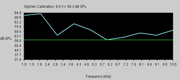
The calibration level is the value that will be used to calculate the normalization curve. It is represented by a green line on the calibration plot. If the SPL at a given frequency is greater than the calibration level, this will result in a negative normalization value. Likewise, if the SPL is less than the calibration level, this will result in a positive normalization value that will be added to the signal to boost it so that it equals the calibration value.
After the calibration is run, the calibration level will be automatically set as high as possible so that the resulting normalization curve does not produce clipping in the DAC when it is used in SigGenRP.
The calibration level will give you the calibration value to use in SigGenRP. For example, if a 9 V test signal was used, the calibration may say 9 V = 110 dB. As you adjust the line, you will see this calibration value change.
Changing the Calibration Level
In most cases you will find that the calibration level is set just as you need. To change the calibration level, left-click on the green calibration line and drag it to a new value. A new normalization curve will be calculated based on the calibration line.
Clipping
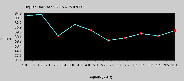
If you set the calibration level too high, so that the normalized signal would be clipped (i.e. the normalization curve would cause the signal to be larger than 10 V), red squares will be placed on the calibration curve at frequencies that will be clipped.
Too Much Attenuation
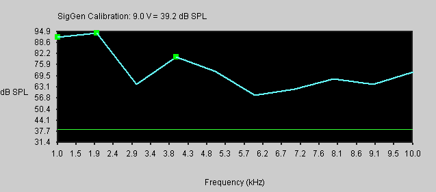
If you set the calibration level too low, so that the output signal would be less than 0.1 V, green squares will be placed on the curve.
Viewing the Normalization Curve
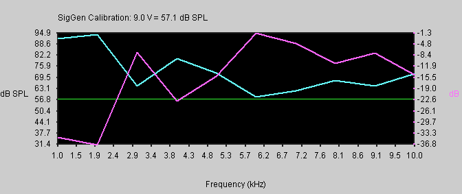
To view the normalization curve, select Normalization Curve from the View menu. The normalization curve will be autoscaled so that it is maximized on the plot. The scale for the normalization curve is labeled on the second y axis, and will be plotted in a fuchsia color.
Testing the Calibration
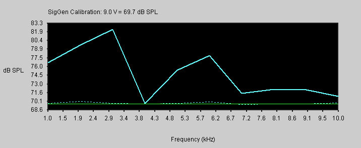
Once the calibration has been run and the normalization curve generated, you can test the normalization curve. Select Test Norm from the Calibration menu. This will use the normalization curve to adjust the signal produced by the DAC.
The level of the sound will be plotted as a dotted line. If the normalization curve is set properly, the dotted line should closely parallel the green calibration line.
Fine Tuning the Calibration
If the calibration test shows that the normalization curve does not produce a flat response out of the speaker:
-
Check to make sure that you are not overdriving the speaker. Look at the THD levels and the power spectra to make sure that you are getting a pure tone signal, and not a lot of harmonics. If you see a lot of harmonics, you either should turn down the gain on your speaker amplifier, or attenuate the signal from the DAC by sending it through a PA5 Programmable Attenuator.
-
Make sure that the microphone is not being overdriven, and that the amplitude of the signal coming out of the microphone amplifier is at least one volt (look at the voltage on the Time Domain plot), but not more than 10 V.
-
Try iterating the normalization test several times. This will adjust the normalization curve based on the deviations from the calibration level.
-
Try re-running the entire calibration with more averages and/or a longer FFT.
If you can't get one normalization file that covers the whole frequency range of the speaker without either clipping the signal or playing too small a signal out of the DAC:
- Break your frequency range into two parts, and create a normalization file for each section.
- You will also have to create a separate SigGen file with a different calibration for each section.
Using Normalization Files in SigGenRP
Once you have established the reasonable frequency range to use for your speaker, run the calibration with smaller steps, and test it. When you are satisfied that the normalization file produces a sufficiently flat response, save your normalization file by selecting Save Norm from the Calibration menu.
The file can then be used in SigGenRP by checking Use Norm in the Signal Parameters dialog box (opened by selecting Signal from the Modify menu), and then loading the normalization file.
Important
Be sure that to generate signals using the frequency method in the segment dialog box. Otherwise, the normalization file will not be used.
Remember to change the calibration setting in SigGenRP to the value determined by SigCalRP. If a SigGenRP variable is used to generate the tone frequency series, the calibrated value determined by SigCalRP may be saved to that SigGen file or a new SigGen file from SigCalRP. For example, if SigCalRP determines that 9.0 V = 105.5 dB. This calibration may be saved to the SigGen file by choosing Save SigGen file. This would modify the calibration values that you see in the SigGen Signal dialog box (opened by choosing Signal from the Modify menu in SigGenRP). If you did not use a SigGen file to set up the frequency series, you would have to manually enter this calibration in SigGenRP.
Using a PA5 Attenuator for Tone Calibration
Calibration of Tone Signals
Normalization files are of most utility for non-tonal signals. If you are using single tones as your SigGenRP stimuli, then you will obtain better signal quality if you use the PA5 Programmable Attenuator to equalize the different frequencies. SigGenRP normalization files adjust for the transducer variability by decreasing the amplitude of the D/A output. When tones are used, since you are only playing one frequency, you can use the PA5 to adjust the signal level. This will provide constant signal-to-noise ratio for all of the frequencies and let you maximize the output voltage on the D/A converter.
Use the Save Variable Schedule File feature of SigCalRP to save these values to a variable file for use in SigGenRP. The values saved to these files will be the attenuations that need to be applied at each frequency to calibrate the signal. In SigGenRP, use this variable file to attenuate each frequency appropriately.
The schedule file creates two lists of values, one for frequencies and one for the normalized attenuation level. You must create two variables in your SigGen file and name them Freq and CalAtten. Set each variable to use the "Schedule File" method and enter the name of the schedule file that you saved after calibration. These two variables will use the list of values saved in the schedule file. Select Preview Variables to confirm the correct values.
Next you must link the appropriate signal parameters to these variables. In the Modify → Segment menu, the frequency of your tone segment should be set to the Freq variable. In the Attenuation box located in the Modify → Signal menu, choose the PA5 device and select the CalAtten variable from the dropdown list. See the SigGenRP help guide for more information.