Lux LEDs and Photosensors
Lux Overview
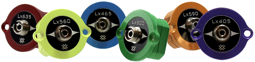
Lux optical components are modular plug-in light sources and photosensors.
They include integrated LEDs, photosensors, M8 connectors for external LEDs,
and BNC for voltage. They can be installed in an RZ10x or iX6 module.
The Lux components are held in place with two nylon screws. They are
interchangeable, so you can swap LED colors at any time, upgrade from an
external photosensor to a PS1 or PS2 integrated sensor, or interface with an
external device with a BNC connector. In the case of lost Lux screws, do not
replace them with metal screws. Please contact TDT support for replacement
screw options.
Important
Make sure the RZ10x or iX6 is powered off before changing the Lux components.
| Lux Pod |
Description |
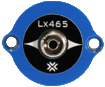 |
Each Lux LED pod is colored with the closest visible color to the wavelength of light it emits. The Lux LEDs can occupy the left three slots of each Lux bank. The 465nm Lux LED is shown at left. |
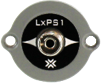 |
The PS1 photosensor measures the fluorescence response from the subject. It can occupy the right two slots of each Lux bank. |
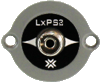 |
The PS2 photosensor is an upgraded version of the PS1 with a ~2x increase in signal-to-noise. |
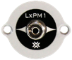 |
The PM1 Power Meter measures the LED power received by the subject. It has built-in fluorescing material so it can also mimic a subject response for full end-to-end system testing. The PM1 can only occupy the slot on the far right of each Lux bank. |
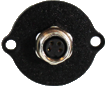 |
The M8 connector is the default placeholder for the left three slots if LEDs aren't installed. It is used to drive an external third-party LED. |
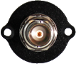 |
The BNC connector can be swapped into any location on the Lux bank to connect to third party devices. It is the default placeholder for the right two slots if PS1/PS2/PM1s aren't installed. |
Important
The Lux LEDs, PS1, PS2, and PM1 have an FC connector with a small key that must be
aligned to the fiber optic cable. This key is in the 10 o'clock position on all
TDT optical Lux components.
See the Synapse Manual for RZ10x
or Synapse Manual for iX6
for information on controlling the Lux drivers and reading the sensors.
Adding or Removing Lux Pods
Before removing or installing any Lux pods, make sure the RZ10x or iX6 is powered off. Make sure that
the pods are oriented with the text right side up and use the nylon screws that came with the system.
If you have trouble holding the pod in the socket while screwing it in, you can connect a fiber optic
cable to it to use as a kind of handle.
When finished, power on the unit. In Synapse, click the detect hardware button on the
RZ10x LUX tab
or the iX6 Options and verify
that the new pods are detected properly.
Lux Technical Specifications
| LEDs |
|
| Available Wavelengths |
385 nm, 405 nm, 415 nm, 450 nm, 465 nm,
500 nm, 530 nm, 560 nm, 590 nm, 615 nm,
635 nm, 850 nm, 940 nm, 5K |
| Current Range |
RZ10x: 2 mA - 1000 mA
iX6: 2 mA - 500 mA
|
| PS1/PS2 |
|
| Bandwidth |
DC - 700 Hz |
| Wavelength Range |
320 nm - 1100 nm |
| Gain |
1e10 |
| PM1 |
|
| Bandwidth |
DC - 3000 Hz |
| Wavelength Range |
320 nm - 1100 nm |
| Gain |
6.5e4 |
| BNC Output Pod |
*RZ10x only |
| Output Channels |
Up to 6 channels, 16-bit PCM |
| Sample Rate |
Up to 48828.125 Hz |
| Frequency Response |
DC - 0.44*Fs (Fs = sample rate) |
| Voltage Out |
±10.0 V, 6 mA max load |
| S/N (typical) |
82 dB (20 Hz - 20 kHz at 9.9 V) |
| Output Impedance |
See below |
| BNC Input Pod |
|
| Input Channels |
iX6: up to 2 channels, 16-bit PCM
RZ10x: up to 4 channels, 16-bit PCM |
| Sample Rate |
Up to 48828.125 Hz |
| Frequency Response |
DC - 7.5 kHz (2nd order, 12 dB per octave) |
| Gain |
RZ10x: 1x
iX6: 1.7x |
| Scale Factor |
RZ10x: 1x
iX6: -10x |
| Voltage In |
RZ10x: ±10.0 V
iX6: ±2.2 V |
| S/N (typical) |
82 dB (20 Hz - 20 kHz at 9.9 V) |
| Input Impedance |
10 kOhms (impedance of input connection
will appear to be ~400 Ohm higher) |
 |
|
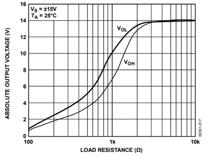
Lux BNC Pod Output Impedance |
 |
|
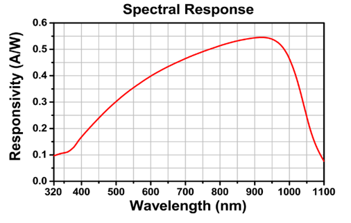
PS1, PS2, and PM1 Responsivity |