ZIF-Clip® Based Microwire Arrays
ZIF-Clip® microwire arrays are made to user specifications. All arrays use polyimide-insulated tungsten microwire which yield excellent recording characteristics and ample rigidity to facilitate insertion.
The standard ZIF2010 resin form factor array consists of sixteen channels configured in two rows of eight electrodes each. The ZIF2012-AL adds an aluminum shroud to provide increased durability. Both types of probes connect to our ZIF-Clip® headstage. When determining insertion spacing between two or more arrays, be sure to consider the headstage dimensions to ensure sufficient clearance.
Note
This section provides information specific to TDT arrays. For more general information see Suggestions for Microwire Insertion.
Part Numbers:
ZIF2005, ZIF2010, ZIF2011, ZIF2020, ZIF2030
ZIF2010-AL, ZIF2011-AL, ZIF2030-AL
ZIF2010-16, ZIF2010-16-AL, ZIF2010-32, ZIF2010-32-AL
ZIF2011-16, ZIF2011-16-AL, ZIF2011-32, ZIF2011-32-AL
ZIF2030-16, ZIF2030-16-AL, ZIF2030-32, ZIF2030-32-AL
ZIF3011-64, ZIF3011-64-AL
ZIF3030, ZIF3030-AL, ZIF3030-64, ZIF3030-64-AL
Connecting to a Headstage
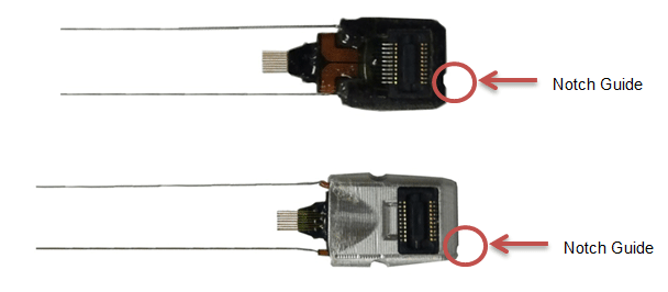
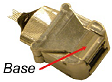
A notch at the base of the array facilitates proper connection to the ZIF-Clip® headstage and can help the user identify the correct mapping of electrodes. Ensure that the notch side is properly aligned with the arrow symbol on the headstage. See ZIF-Clip® Adapter and Probe Connection for images and instructions.
Bonding the Arrays
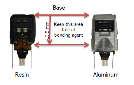
After insertion, ensure acrylic or other bonding agent does not come into direct contact with the active circuitry. Bonding agents can cause permanent damage to the array. There should be no bonding agent closer than 10.5 mm to the base.
Grounding the Electrode
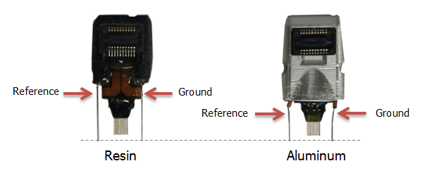
The images below show the possible connections made for reference or ground wires. These wires are attached at TDT.
Caution
The ZIF resin (no-aluminum shroud) microwire arrays can be damaged by extreme heat. Use caution when soldering.
ZIF-Clip® Based Microwire Array Specifications
Specifications might vary based on custom order:
See the Online Order Form for more information on ordering specifications.
ZIF-Clip® Based Microwire Array Site Map
The following diagrams illustrate the site map configurations for 16, 32, and 64 channel ZIF-Clip® based microwire arrays. Site numbers reflect the site map or channel output to a TDT amplifier from the ZIF-Clip® based microwire array (when connected with a ZIF-Clip® headstage).
16 and 32 Channel ZIF-Clip® Microwire Arrays
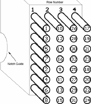 |
| Channel numbers are looking into array |
Note
16 channel ZIF-Clip® based microwire arrays contain only the first 2 rows.
64 Channel ZIF-Clip® Microwire Array
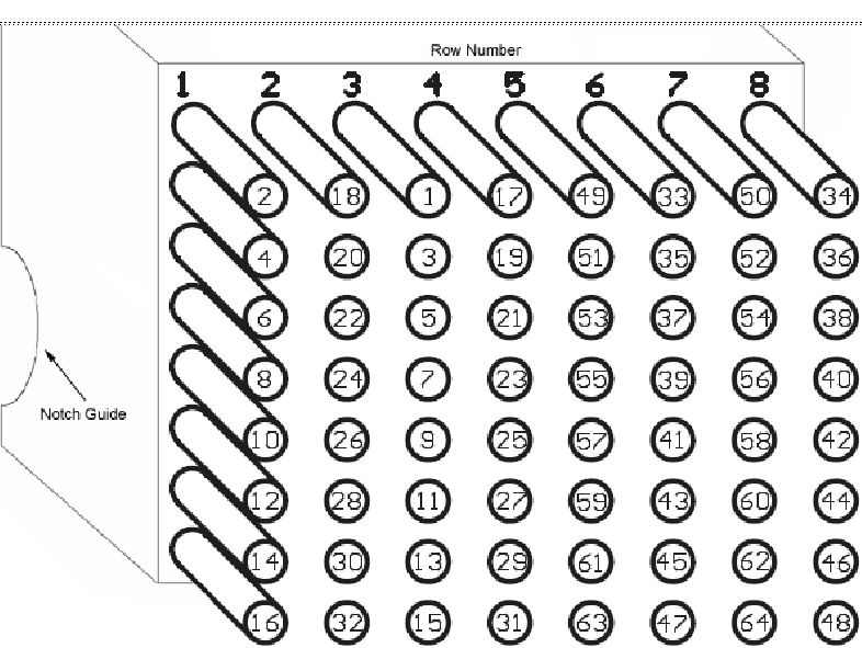 |
| Channel numbers are looking into array |
Z-CAP - Aluminum ZIF-Clip® Cap
The ZIF-Clip® Caps are made of high quality aluminum and are designed to protect the ZIF-Clip® micro connector from potential damage in the absence of the ZIF-Clip® headstage. They can be used with both ZIF-Clip® probe adapters and microwire arrays.
Part Number: Z-CAP32, Z-CAP64, ZL-CAP32, ZL-CAP64
The Z-CAP Standard Cap

The Z-CAP fits directly over all resin form factor ZIF-Clip® compatible connectors and features a rubber O-ring for easy handling and grip.
To use the Z-CAP:
- Grip it with two fingers and gently slide it onto the ZIF-Clip® micro connector.
To remove the Z-CAP:
- Grasp both sides of the O-ring grip and gently pull away from the ZIF-Clip® micro connector until the Z-CAP releases from the connector.
The ZL-CAP Locking Cap
The ZL-CAP can only be used with aluminum form factor ZIF-Clip® arrays. It locks onto the shroud to prevent unintentional removal of the cap by the subject when not in use. Aluminum shroud arrays and locking caps are recommended for larger test subjects.
To use the ZL-CAP:
-
Pinch the base with two fingers and gently slide it onto the ZIF-Clip® connector.
-
Pinch the opposite end of the connector to engage the locking clamp.
To remove the ZL-CAP:
- Pinch the base with two fingers to open the locking clamp and gently slide it off of the ZIF-Clip® connector.