UZ2 USB 2.0 Interface
 |
| UZ2 Interface |
Overview
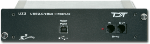
The USB 2.0 zBus Interface mounts in the rear bay of a zBus device chassis and handles communication and data transfer between your computer and zBus mounted programmable devices, such real-time processors or programmable attenuators. Most nonprogrammable devices, such as speaker drivers or signal mixers, do not require an interface.
You will need a USB 2.0 port available on the host PC for each UZ2 in a multi-chassis system. We recommend upgrading to an Optibit interface if your system requires more than three chassis.
Note
If using the USB 2.0 interface on a 64-bit operating system, you must install version 76 TDT drivers or greater.
Connecting the UZ2
The UZ2 connects to your computer with standard USB 2.0 A to B cables (provided with each module). Interface drivers are bundled with the TDT Drivers and will be installed when the device is connected to the host computer for the first time. The UZ2 can be safely connected or unconnected while the computer is running.
Important
Wait 10 seconds after devices have gone through the boot sequence or 30 seconds after turning on devices (with the computer already running) before running applications that use TDT devices. We also recommend using zBUSMon to verify the logical order of devices before beginning any experiment. See Boot Up Sequence for more information.
Sync
The Sync input allows users to synchronize several modules that are mounted in different device chassis. Each USB module has its own clock. Clocks on multiple USB devices will drift relative to each other. The Sync line uses the clock from one USB module, the parent, to synchronize the clocks across all zBus device chassis.
To connect several zBus chassis, one module (the highest logical module) is designated as the parent and the other clocks are children of the master clock. Connect the Sync Out of the parent clock to the Sync In of the child with a short patch cable. To connect several device chassis, daisy-chain the connections between the child chassis. When the Sync lines are connected correctly the LED to the left of the Sync connectors should be lit on each child device. The LED on the parent will remain unlit. The LED should only flash when the Sync lines are not connected.
Logical Order of Devices
The logical order of devices is determined each time the zBus chassis are powered on. You can verify the current logical order using the zBUSMon utility.
Boot Up Sequence
The boot up sequence for the USB 2.0 interface is driven from the PC and follows the communication protocol described below.
The first time the hardware is turned on:
-
A device driver is loaded to the interface. Depending on your operating system, the PC might beep to indicate that the device driver has been loaded.
-
A second set of drivers will be loaded and the devices will reboot.
-
The TDT hardware is queried to determine the logical order of the devices and zBus chassis.
Important
If the zBus is accessed during step 3, the devices will fail to ID. To ensure that step 3 is completed, wait 10 seconds after the devices have rebooted (step two) before loading any TDT application or viewing the devices in zBUSMon. If the hardware fails to identify, power down the TDT hardware and restart it.
UZ2 Technical Specifications
Interface transfer rates vary by transfer type and device. See Interface Transfer Rates for more information.