RZ-UDP Communications Interface
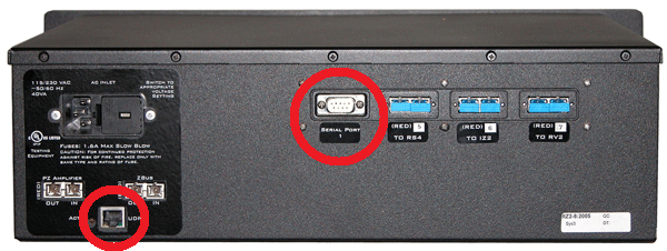 |
| RZ2 Processor Back side with RZ-UDP Installed |
RZ-UDP Overview
The RZ Communications Interface (RZ-UDP-20) is an optional interface for RZ processor devices that includes a UDP Ethernet connection and a serial port connection.
The serial port can support baud rates up to 115200. The port is a standard 9-pin RS232 connection located on the back of the RZ. The RS232 port can be directly connected to any device that communicates via serial port, such as head trackers, eye trackers, or a PC.
Note
If the RZ has four optical DSP cards, the serial port is not available.
The UDP interface is designed to transfer up to 200 data values at low rates to or from a PC. The PC may be directly connected through a dedicated Ethernet card located elsewhere on the user's network, or even in a remote location connected via the Internet. The RZ UDP interface is located on the back panel of the RZ processor and accepts a standard Ethernet cable.
Like all network devices, the RZ UDP interface utilizes several network parameters such as a unique network address, appropriate network mask, and optionally a gateway (if operating across networks). The RZ UDP Ethernet interface supports the DHCP (Dynamic Host Configuration) protocol for automatic configuration of these network parameters, but these parameters may also be set manually, as described in Configuring the UDP. The type and structure of data for the serial port must be manually configured through the same network interface.
Note
The RZ-UDP-20 is an updated version of the RZ-UDP-10 which had only an Ethernet interface. Configuration of the Ethernet interface is the same for both versions.
RZ-UDP Basics
Setting-Up Your Hardware
To setup the UDP Ethernet interface, connect your Ethernet cable directly to a PC Ethernet port or standard Ethernet wall jack. For more information on setting up or configuring the RZ processor see the System 3 Installation Guide.
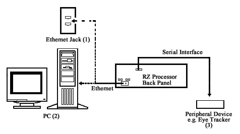
The diagram above illustrates the possible connections from the RZ processor to an active network (1) or PC (2), and an optional serial connection to a peripheral device (3).
Note
If you are only using the serial interface, you will still need a UDP Ethernet connection to configure the serial interface through the web interface. See Configuring the UDP through the Web Interface for more information.
Programming Configuration
Synapse has built-in objects for the Processing Tree to send and receive data from the UDP interface. These must be added to your Hardware Rig in Synapse and then simply connect the desired signal stream to the UDP object. See the Synapse Manual for more information.
For RPvdsEx circuit design, two macros designed for the UDP Ethernet interface and two macros for the serial interface are installed here:
C:\TDT\RPvdsEx\Macros\Device\UDP Ethernet\
Status LEDs
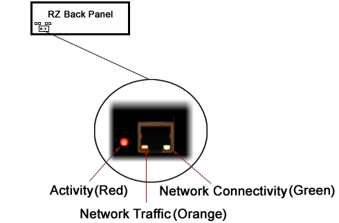
The following table lists the possible status indicators for the UDP Ethernet interface.
UDP Configuration
The UDP interface has a unique IP address and network mask.
DHCP protocol automatically assigns IP addresses to devices on the network. The UDP interface relies primarily on dynamic mode for its IP configuration.
The UDP interface has a unique MAC address. You may need to know the MAC address for the UDP interface if you are connecting this device to the building network, so the IT department can let the UDP interface on the network. See Direct Connection to a PC for instructions on connecting a PC directly to the UDP interface so you can get the MAC address through the UDP web interface.
Background Information
UDP or "User Datagram Protocol" is a core protocol of the Internet Protocol suite or more commonly known as the TCP/IP protocol suite. UDP allows programs and networked computers to send datagrams or data organized in a specific structure (commonly referred to as a packet).
Note
The UDP protocol is considered "connectionless" since devices send data to a defined IP address and are not actively connected to the destination device or PC. As such, the UDP Ethernet interface will send or receive data from the last IP address it is configured to communicate with.
When information from a data protocol (UDP or TCP) is sent, the information may get lost or delayed along the way. UDP protocol allows time critical data to be transmitted with very low latency since UDP protocol does not implement data tracking. Conversely, when TCP detects that information has been lost or received out of order, it resends the suspect information. This is insufficient for time dependent data found in most neuroscience applications.
Note
The UDP protocol does not account for data received out of order.
Initialization
Upon initializing, the UDP interface will attempt to locate a DHCP server to dynamically assign an IP address to the device. If a DHCP server is available, a dynamically allocated IP address is assigned to the interface. If no DHCP server responds, the device falls back on the following static IP configuration:
NetBIOS Name
You can connect to the UDP interface with either the IP address or the NetBIOS name, similar to how you can access computers on your network by name or IP address. The default NetBIOS name associated with the IP address is set by TDT and has the following naming structure:
For Example, an RZ2-4 (4 DSP) with a serial number of 1234 uses a NetBIOS name
of TDT_UDP_24_1234. An RZ5D with a serial number of 1011 uses a NetBIOS name
of TDT_UDP_D3_1011.
Note
Devices equipped with a UDP interface that have a serial number less than 2012 use a different NetBIOS name format. Use the IP address instead.
Although a default NetBIOS name is assigned. The name can be changed using the UDP Web Interface, see Configuring the UDP through the Web Interface for more information.
Note
When connecting the RZ, be sure the network mask is set to a Class C or smaller network. A Class A network mask (255.0.0.0) will disable NetBIOS naming on the PC Ethernet interface. In such cases, the IP address of the UDP Ethernet interface must be specified instead.
Configuring the UDP through the Web Interface
Every RZ UDP interface contains a minimal web server which is used to configure the UDP and serial interfaces. Configuration options can be set here if no DHCP server is available. If a DHCP server exists, the NetBIOS name associated with the dynamically assigned IP address can be configured here.
Note
The web interface is only enabled for one minute after powering up the RZ, unless it is in use, in which case it remains enabled until the RZ is turned off. Loading pages through the web interface while collecting data is discouraged and may cause packet loss.
To connect to the UDP Ethernet interface server:
-
Make sure there is an active connection from the PC to the UDP Ethernet port on the back of the RZ then open an Internet browser such as Mozilla Firefox.
-
Enter the device's IP address (if known) as the web address (e.g. http://10.1.0.100) or the NetBIOS name as the web address (e.g. TDT_UDP_0000000).
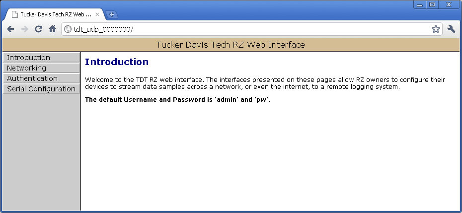
Introduction Page
The Introduction page provides basic information, including the default username and password. The login information can be changed on the Authentication page.
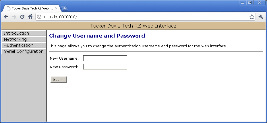
Authentication Page
The Authentication page allows users to change their username and password provided they enter the currently set username and password.
Note
Any server pages that modify the device configuration require a username and password.
Default Username: admin
Default Password: pw
Network Configurations Page
This page contains settings for configuring the UDP interface. To change the network configuration, click the Networking link on the left.
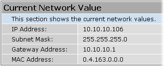
Current Network Value
Network Settings
This area contains settings for configuring the UDP interface in the event that no DHCP server is detected.
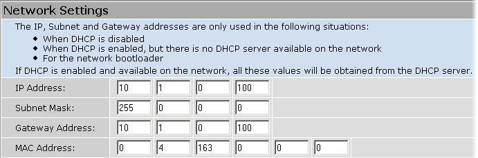
Note
These settings are reserved for connections that cannot locate a DHCP server. If no DHCP server can be detected contact your network administrator for applicable settings. If the 'Enable DHCP' check box is checked (see Parameters below), the "IP Address", "Subnet Mask", and "Gateway Address" values are overridden and automatically configured by the DHCP server if available.
Parameters
This area contains settings for enabling DHCP or renaming the NetBIOS name.
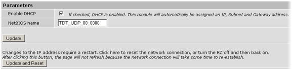
The Update and Reset button saves the current configuration settings and performs a soft reset of the UDP interface to load the current settings.
Note
The NetBIOS name can be no greater than 15 characters long and cannot contain spaces or the following characters: / : * ? " ; | -
Note
A reset circuit is provided with the TDT driver installation and can be found in:
C:/TDT/RPvdsEx/Support/
Running this circuit on the device with the UDP interface will reset the NetBIOS name to the factory default setting described in NetBIOS Name.
Direct Connection to a PC
The UDP interface can be connected directly to a PC or laptop. Once connected, several steps are required in order for the PC to recognize to the UDP interface connection. This method may be performed on any operating system which supports TCP/IP.
To initialize the PC for a direct connection in Windows 10:
-
Physically connect the UDP interface and the PC via an Ethernet cable.
-
Open Control Panel then double-click Network and Sharing Center.
-
Click the desired connection link (this is usually a Local Area Connection).
-
In the status dialog, click the Properties button.
-
In the item list, select Internet Protocol (TCP/IP) or if there are multiples, select Internet Protocol (TCP/IPv4).
-
Click the Properties button.
-
Select Use the following IP address and enter these values:
IP address: 10.1.0.x, where x can be any value, 1 to 254, except 100
Subnet mask: 255.255.255.0
Default gateway: Leave empty
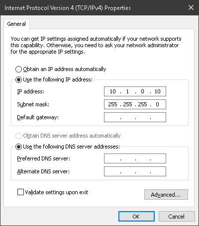
-
Click OK.
The UDP interface connection should now be recognized by the PC. Cycle power on the RZ device, the IP address of the RZ will be 10.1.0.100.
Serial Configuration Page
Note
If the RZ has four optical DSP cards, the serial port is not available.
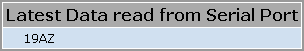
Latest Data Read from Serial Port
If any data has been sent to the RZ serial port, the latest value will be displayed in this area. ASCII characters represent each byte.
Settings for enabling the serial port, setting baud rate, setting data type and command formats are located in the Serial Port Settings area.
Parameters
The user can enable/disable the serial port, specify the baud rate, and select from a list of preset values.
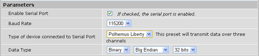
Data Type
Big vs Little Endian
If the device attached to the RS232 connection sends the lower byte before the upper byte, set this to Little Endian. Otherwise, use Big Endian.
8 vs 16 vs 24 vs 32 bit words
This field specifies the length of the data words that the device attached to the RS232 connection is sending. If the data being received is less than 32 bits in length, it is 0 padded out to 32 bits.
Response Format
This area contains configuration settings for the data received from the peripheral device. As data is received over the RS232 connection, it is matched against a user-specified sequence of header bytes at user specified intervals. For example, the user could set the connection to match two specific header bytes, process the next four bytes as data and then start the process over again.
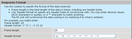
Frame Length
Enter the total length of a 'frame' of data, including any header bytes. In the example shown in the image above, three channels of 32 bit data are being sent, for a total of 12 data bytes (32 bits = 4 bytes). In addition, there are 8 'header' bytes that the user wants to synchronize with, bringing the total frame byte count to 20. The Frame Length, the word size, and the size of the header bytes are used to determine the number of channels being sent and which channel each data byte belongs to.
Header Format
If this field is empty, no synchronization will occur, and everything sent over the RS232 connection will be processed. Otherwise, the RZ will look for the specified sequence of bytes at the beginning of each frame. The user can enter a decimal value or any ASCII character in single quotes (e.g. 'A'). The '*' character is reserved as a wildcard character that will match anything.
Note
If the received data/headers do not match the expected format, they are discarded and all synchronization information is reset. The RZ will then wait until 10 consecutive successful synchronizations before processing any further data bytes.
Commands
This area is used to configure any commands that the RZ needs to send over the serial port. Use this section if the peripheral device connected to the RS232 accepts special requests, such as an initialization command, start/stop command, or reset command.
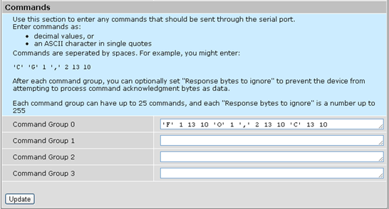
Command Groups
The format of this section is similar to the header format. The user can enter a decimal value or any ASCII character in single quotes, but the '*' no longer takes on any special meaning here. Each of the command groups is tied to a trigger in the RZ_Serial_Rec or RZ_Serial_Send macros. When triggered, the specified sequence of bytes/characters will be sent over the RS232 connection.
Configuring the UDP Interface on the RZ
Synapse has a built-in object for the Processing Tree to stream packets to/from the UDP interface. This must be added to your Hardware Rig in Synapse by right-clicking on the RZ in the Rig Editor. See the Synapse Manual for more information.
Note
For RPvdsEx circuit design (OpenEx users), the TDT drivers installs the UDP
circuit macros in C:\TDT\RPvdsEx\Macros\Device\UDP Ethernet\. See
the Legacy System 3 Manual
for circuit design.
Note
The RS232 serial port must use the RZ_Serial_Rec or RZ_Serial_Send macros in RPvdsEx.
Programming Guide
Wrapper classes and demo files for MATLAB and Python are in the RZUDP Programming Guide A C# implementation can be found on github. A C++ example is available on request.
UDP Interface Performance
The UDP interface is a 10Mb Ethernet interface, but the usable bandwidth is significantly lower due to limitations of the Ethernet hardware. A graph below displays the expected throughput for different numbers of packets sent or received per second depending on the number of channels transmitted on an RZ processor.
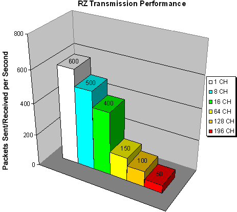
The bandwidth for transmitting data from an RZ through the UDP interface decreases depending on the width (or number of channels) of packets sent or received. Transmission of a single packet (single channel) provides a high amount of data resolution since the packets are transmitted at a much higher rate and would respond quickly to abrupt changes in value. Transmitting multiple packets (large number of channels) allows more information to be sent in parallel but reduces data resolution.
Relative Performance
A typical application might involve sending a packet size of 16 channels 100 times per second or a packet size of 100 channels 10 times per second. As shown in the diagram above, the UDP interface will be able to send a packet size of 16 channels 400 times per second or a packet size of 128 channels 100 times per second.
As a result, the UDP performance is relative to the size of the packet, dictated by the number of channels transmitted.
Typical RZ Transmission Performance with the RZUDP-20 Table
The table below displays the expected throughput for different numbers of packets sent or received per second depending on the number of channels transmitted on an RZ processor.
RZ-UDP Technical Specifications
Appendix I: UDP Test Application
A software test application installs with the TDT Drivers and can be used to send or receive packets from an RZ UDP interface. The UDP Test Application installs to:
C:\TDT\RPvdsEx\Examples\RZ UDP\
Running the Application
Once the application is running, connect to a UDP interface for sending or receiving packets from an RZ processor. Packets can be loaded, saved, and edited. Additionally, the packet format can be converted to double or integer format.
To create a new packet:
-
Double-click anywhere in the packet window to access the Edit Values dialog box.
or
Right-click the packet window to access the Packet Dialog menu.
-
Select the New Packet option. This prompts the Edit Values dialog box.
To edit an existing packet:
-
Select the desired packet and right-click to access the Packet Dialog menu.
-
Select the Edit Packet option. This prompts the Edit Values dialog box.
To convert the UDP Test Application packet format:
-
Right-click the packet window to access the Packet Dialog menu.
-
Select Convert To.
-
Select the desired format for the selected packet.
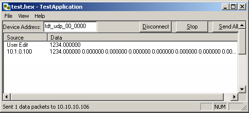
Example: Using the UDP Test Application
In this example we will send packets from the PC to an RZ through the UDP interface.
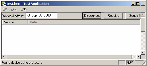
To establish a connection to the RZ:
-
First, run the UDP Test Application by double-clicking the UDPTestApplication.exe icon.
-
Enter the NetBIOS name or IP address of the RZ processor you wish to send a packet to in the Device Address text box.
-
Click the Check button.
A connection is established and the status bar indicates a device has been found. Packets may now be received or sent from this RZ processor.
To send a data packet to the RZ processor:
-
Double-click anywhere in the UDP Test Application packet window.
or
Right-click to bring up a selection dialog box and select New Packet.
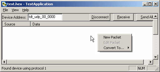
This prompts a dialog box where values can be edited.
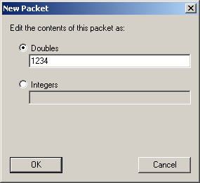
-
Click the Doubles radio button and enter "1234".
-
Click OK.
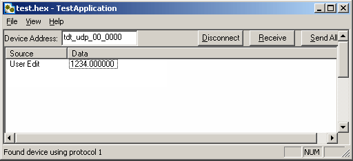
The configured data packet is shown in the UDP Test Application packet window.
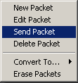
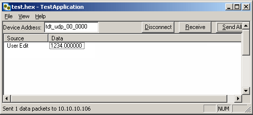
-
Click the Send All button to send all data packets to the RZ processor.
or
Send an individual packet by right-clicking on the desired packet and selecting Send Packet from the Packet Dialog menu.
To receive a data packet sent from the RZ processor:
-
First, run the UDP Test Application by double-clicking the UDPTestApplication.exe icon.
-
Enter the NetBIOS name or IP address of the RZ processor you wish to send a packet to in the Device Address text box.
-
Click the Check button.
-
Click the Receive button.
The button changes to Stop in order to notify that it is waiting for a data packet to be sent from the RZ processor. Data packets are sent through the Synapse UDPSend Hal, or from RPvdsEx using the RZ_UDP_Send macro.
-
At this time you may configure the circuit to send a data packet from the RZ processor to the UDP Test Application.
Once received, the data packet will be displayed in the UDP Test Application packet window. The Source column will display the IP address the data packet was received from while the Data column displays the data packet itself.
Appendix II: Network Structure
In order to understand how the UDP interface works, a basic understanding of Internet Protocol (IP) networking is required. As mentioned above, all network devices require a unique network address, appropriate network mask, and if communicating between networks, a gateway. Data in IP networks is organized into discrete packets for transmission or reception. For our purposes, the packet size is equivalent to the number of channels being transmitted or received.
Network Address
All network devices utilize a network address commonly referred to as the "IP address". The IP address is a unique address given to any networked device and consists of four hexadecimal values that are used to locate a device from within a network. Multiple devices that are located within a common network use similar IP addresses.
For example:
Several office computers are connected to a network within an office.
IP address Computer 1: 192.86.100.10
IP address Computer 2: 192.86.100.11
IP address Computer 14: 192.86.100.23
As shown above, IP addresses share a common prefix when located on a common network.
Dynamic Host Configuration Protocol (DHCP), for instance, requires that broadcasts be used to dynamically assign a unique IP address to computers on a network.
MAC Address
A device's MAC address or "Media Access Control" address is a unique number that acts like a name for a particular network adapter. On a shared medium such as Ethernet, this address is generally assigned to the hardware when it is constructed, but may be manually modified in the UDP Interface.
For example:
The network cards in two different computers will have different MAC addresses, as would an Ethernet adapter and a wireless adapter in the same computer.
The DHCP Protocol
DHCP or "Dynamic Host Configuration Protocol" is a protocol used by networked devices (clients) to obtain various parameters necessary for the clients to operate in an Internet Protocol (IP) network. By using this protocol, system administration workload greatly decreases, and devices can be added to the network with minimal or no manual configuration.
DHCP automates the assignment of IP addresses, subnet masks, default gateway, and other IP parameters. Three modes for allocating IP addresses exist: dynamic, reserved, and manual. The UDP interface relies primarily on dynamic mode for its IP configuration.
Dynamic
In dynamic mode a client is provided with a temporary IP address for a given length of time. This length of time is dependent on the server configuration and may range from a long time (months) to several hours.
The current IP address can be renewed at any time by the DHCP client. This renewal is used by properly functioning clients to maintain the same IP address throughout their connection to a network.
Appendix III: The UDP Protocol
UDP or "User Datagram Protocol" is a core protocol of the Internet Protocol suite or more commonly known as the TCP/IP protocol suite. UDP allows programs and networked computers to send datagrams or data organized in a specific structure (commonly referred to as a packet).
Note
The UDP protocol is considered "connectionless" since devices send data to a defined IP address and are not actively connected to the destination device or PC. As such, the UDP Ethernet interface will send or receive data from the last IP address it is configured to communicate with.
When information from a data protocol (UDP or TCP) is sent, the information may get lost or delayed along the way. UDP protocol allows time critical data to be transmitted with very low latency since UDP protocol does not implement data tracking. Conversely, when TCP detects that information has been lost or received out of order, it resends the suspect information. This is insufficient for time dependent data found in most neuroscience applications.
Note
The UDP protocol does not account for data received out of order.
The UDP Packet Structure
All data sent or received by the UDP Ethernet interface is in the form of a packet. Every packet has a standard structure which includes a 4 byte header followed by n x 4 bytes of data, where n is the total number of channels.
Note
The term packet refers to a header and number of single sample values sent. Each channel sends a single sample. The packet size is therefore equivalent to the number of channels and is measured in 32-bit words.
For Example:
Sending 16 channels (a packet size of 16, 32-bit words) will produce a packet of 68 bytes.
4 byte header + (16 channels x 4 bytes) = 68 bytes.
Header Format
The packet header precedes a new packet and stores information about the packet and its intended command for the UDP interface. The structure for the packet header is shown below.
4 Byte Packet Header (32 bits)
The upper two bytes, "55AA" are reserved and required by hardware. The lower two bytes are used for specifying a UDP command (Cmd) and the number of 4 byte data packets (Num) that are to be expected following the header. For all data samples, "Cmd" must be set to 0.
For Example:
The previous example which sent a packet size of 16 channels would use the 32-bit header:
Where the "Num" value 0x10 = 16 (the number of channels).
UDP Interface Commands
There are 4 commands that can be specified for the header byte labeled "Cmd".
Appendix IV: Serial Circuit Design
Access to the Serial interface is provided through two RPvdsEx macros: RZ_Serial_Send and RZ_Serial_Rec. Both macros operate on multi-channel data and can be configured to specify the number of channels. This channel count corresponds to the size of the underlying serial stream.
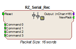
RZ_Serial_Rec Macro
The RZ_Serial_Rec macro is used to receive serial data from the RS232 connection and can also be triggered to send preset commands over the RS232 connection. The number of channels received by the hardware is set in the web configuration. Make sure the packet size set in the macro is at least as large as the value set in the web configuration, otherwise some channels will have missing or incorrect data. If packet size is larger than the number of channels being sent, any excess channels will simply read 0.
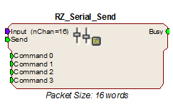
RZ_Serial_Send Macro
Use the RZ_Serial_Send macro to send more than just the pre-configured commands over RS232. If using both the RZ_Serial_Rec and RZ_Serial_Send in the same circuit you must disable the Commands in the RZ_Serial_Rec macro options.
Sending Data Construct
Data is sent whenever the "Send" input receives a rising trigger (logic high (1)). The duration of the busy signal is then dependent on the number of channels to send (packet size). Each logic high pulse sent to the send input results in one send packet request. This means that each packet sent results in one sample sent per channel.
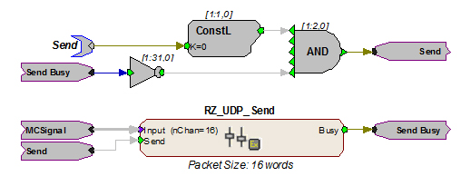
In this construct, the parameter tag "Send" is used to enable data transmission. The Send input on the RZ_UDP_Send macro is only pulsed when the Send parameter tag is high (1) and the macro is not already sending a packet (Busy = low (0)). Data is input from the HopIn component labeled MCSignal.
Note
To modify the number of channels sent, (packet size) edit the Packet Size parameter found in the RZ_UDP_Send macro setup properties.
Receiving Scalar Data Construct
When data is received, the NewPack signal will output a logic high (1) denoting that a packet header has been found. As data is being received, the Busy signal will output a logic high (1) and as soon as the header has been received, NewPack will go low (0). The Busy signal will then remain high until the entire packet has been received. The duration of the busy signal is then dependent on the number of channels to send (packet size). Each high duration of the Busy signal results in one received packet. This means a single packet received results in one sample received per channel.
If reset goes high (1) at any time, receiving data is halted and the macro will wait until a new header is found. Any data that was received will still be available on the multi-channel output.
Note
Since the data packets are received serially, multi-channel data is not received at the same time on the Output. There will be a time shift in channels two and higher directly proportional to the channel number.
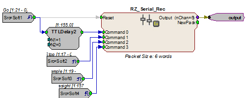
In this circuit construct, software triggers are used to send commands to the peripheral device (head tracker). The multi-channel output contains the tracking information and can be further processed and/or stored to the data tank.