RBOX Response Box
The RBOX has four buttons for user response and four LEDs that can be used to provide a subject with feedback. This small, lightweight response box is an affordable solution for collecting simple subject response data. The RBOX is intended for use as part of a TDT system with a compatible real-time processor providing control and response acquisition. There are several versions of the RBOX, each customized for a particular processor.
Part numbers:
RBOX - Response Box for RP2.1
RBOX4 - Response Box for PI2, RM1, or RM2
RBOX_RX6 - Response Box for RXn
RBOX_RZ6 - Response Box for RZ6
Software Support
PsychRP and SykoFizX software applications for psychophysics provide support for the RBOX. The response box can also be used with custom designed software developed using RPvdsEx and TDT's ActiveX or OpenDeveloper tools, or in Synapse software.
Connecting the RBOX to the Processor
The RBOX must be connected to Digital I/O port on the controlling processor, using the provided cable. The Digital I/O ports on the RP2.1, RXn, and RZ6 (serial numbers >=2000) use a DB25 connector. The Digital I/O ports on the RM1/RM2 and RZ6 (serial numbers <2000) use a DB9 connector.
The RM1/RM2, RXn, and RZ6 processors require additional RPvdsEx software configuration for use with the RBOX. See the corresponding sections below for device specific information.
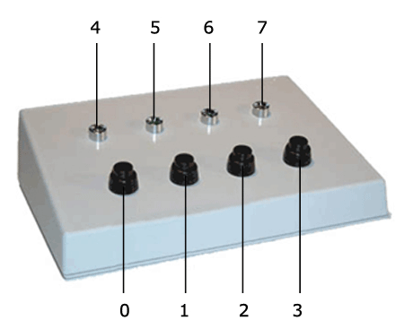
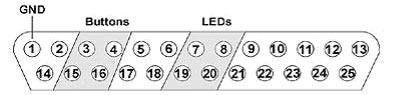
Buttons and LEDs
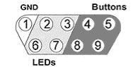
The buttons and LEDs are numbered as follows.
Note that the logic on the inputs to the processors is reversed. Therefore, when polling the lines to determine if a button has been pressed, a logic high or '1' means that no button is pressed and a logic low or '0' indicates a button press.
Configuring the RZ6 Processor for the RBOX_RZ6 in Synapse
The digital I/O is configured in the Synapse RZn Hal. Set Port-C.0 ... Port-C.3 as inputs to read the button presses in Synapse, and Port-C.4 ... Port-C.7 as outputs to drive the LEDs from Synapse.
Configuring the RZ6 Processor for the RBOX_RZ6 in RPvdsEx
The RBOX_RZ6 uses the ground connection (pin 5) and the 8-bits of bit-addressable digital I/O on an RZ6 Digital I/O port. Bits 0 through 3 are used as button inputs and Bits 4 through 7 are used as LED outputs (see Buttons and LEDs).
To use the response box with an RZ6 processor, use RPvdsEx BitIn and BitOut components to address the buttons and LEDs.
Note
Logic inputs are Logic-High by default with open circuit (button not pressed). A button press shorts the input, causing a Logic-Low state.
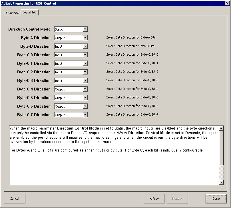
The bit-addressable digital I/O lines can be either inputs or outputs. By default, all are configured for inputs. Modifying the RZ6_Control macro will enable Bits 4-7 to be outputs for driving the LEDs of the RBOX.
To configure the RZ6_Control macro:
-
In RPvdsEx, under the Components Menu, choose Circuit Macros.
-
Navigate to Device\RZ6_Processor and choose RZ6_Control.
-
Click Insert and click the circuit to place the macro.
-
Double-click the newly placed macro to open its properties.
-
Choose the Digital I/O tab.
-
Select Output for bits 4, 5, 6, and 7 to set them all as outputs, as shown below.
Note
Byte-A and Byte-B are not used with the RBOX.
Configuring an RX Processor for the RBOX_RX6 in Synapse
The digital I/O is configured in the Synapse RXn Hal. Set Port-C.0 ... Port-C.3 as inputs to read the button presses in Synapse, and Port-C.4 ... Port-C.7 as outputs to drive the LEDs from Synapse.
Configuring an RX Processor for the RBOX_RX6
The RBOX_RX6 uses the ground connection (pin 5) and the 8-bits of bit-addressable digital I/O on an RX-series processor Digital I/O port. Bits 0 through 3 are used as button inputs and Bits 4 through 7 are used as LED outputs.
To use the response box with an RX processor, configure the bits in the RPvdsEx configuration register as follows:
-
Click the Device Setup command on the Implement menu.
-
In the Set Hardware Parameters dialog box, click the Device Type box and select any RX device from the list.
-
The dialog expands to display the Device Configuration Register.
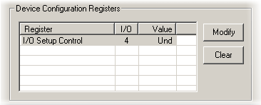
-
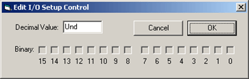
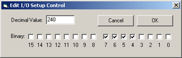
Click Modify to display the Edit I/O Setup Control dialog box. In this dialog box, a series of check boxes are used to create a bitmask that is used to program all bits.
-
To enable the check boxes, delete Und from the Decimal Value box and enter 240. This configures Bits 4 through 7 as outputs.
-
When the configuration is complete, click OK to return to the Set Hardware Parameters dialog box.
Configuring an RM Processor for the RBOX4
The RBOX4 uses the ground connection (pin 1) and the 8 bits of digital I/O on an RM-series processor Digital I/O port. Bits 0 through 3 are used as button inputs and Bits 4 through 7 are used as LED outputs.
To use the response box with an RM processor, configure the bits in the RPvdsEx configuration register as follows:
-
Click the Device Setup command on the Implement menu.
-
In the Set Hardware Parameters dialog box, click the Type drop-down box and select either the RM1 or RM2 from the list.
-
The dialog expands to display the Edit Bit Dir Control dialog box.
-
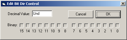
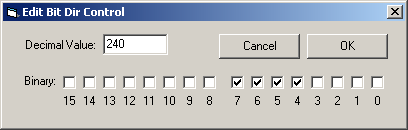
Click Modify to display the Edit Bit Dir Control dialog box. In this dialog box, a series of check boxes are used to create a bitmask that is used to program all bits.
-
To enable the check boxes, delete Und from the Decimal Value box and enter 240. This configures Bits 4 through 7 as outputs.
-
When the configuration is complete, click OK to return to the Set Hardware Parameters dialog box.
Response Box Technical Specifications
RBOX, RBOX_RX6, and RBOX_RZ6 Specifications
Response Box for RP2.1, RXn, and RZ6.
Note
RBOX_RZ6 serial numbers <2000 use a DB9 Connector. See RBOX4 DB9 Connector Pinout.
RBOX DB25 Pinout
RBOX4 Technical Specifications
Response Box for RM1 and RM2.
RBOX4 DB9 Connector Pinout