Preamplifier Adapters
Each TDT headstage is designed for use with either a Legacy or Z-Series preamplifier. Preamplifier adapters allow TDT headstages to be used with a variety of preamplifiers by converting the type of preamplifier connector.
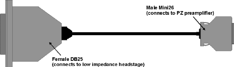
DBF-MiniDBM Low Impedance Headstage to PZ Preamplifier (16-channels)
This adapter connects a low impedance headstage (RA4LI or RA16LI) to a PZ preamplifier.
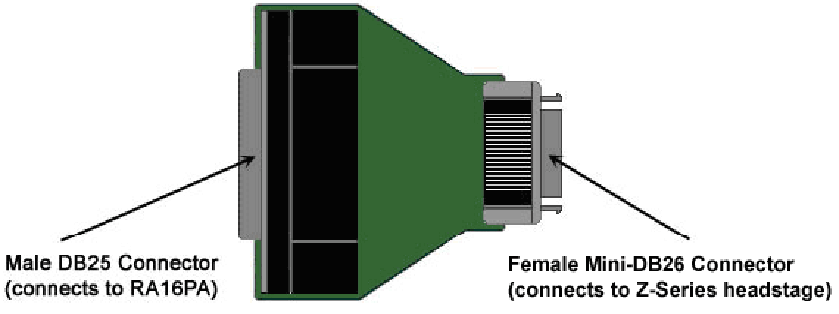
MiniDBF-DBM Z-Series Headstage Female Mini-DB26 to Male DB25 Cable Adapter
This adapter converts a Z-Series headstage Mini-D connector to a DB25 connector for use with a Medusa RA16PA preamplifier.
PLX-ZCA Z-Series Headstage to Plexon Preamplifier
This adapter connects a Z-Series headstage to a Plexon preamplifier. Each PLX- ZCA adapter board connects 16-channels. Multiple adapter boards can be stacked for a higher channel count and are fastened together using two screws on either side of the adapter board. An external power source is provided to power the headstage.
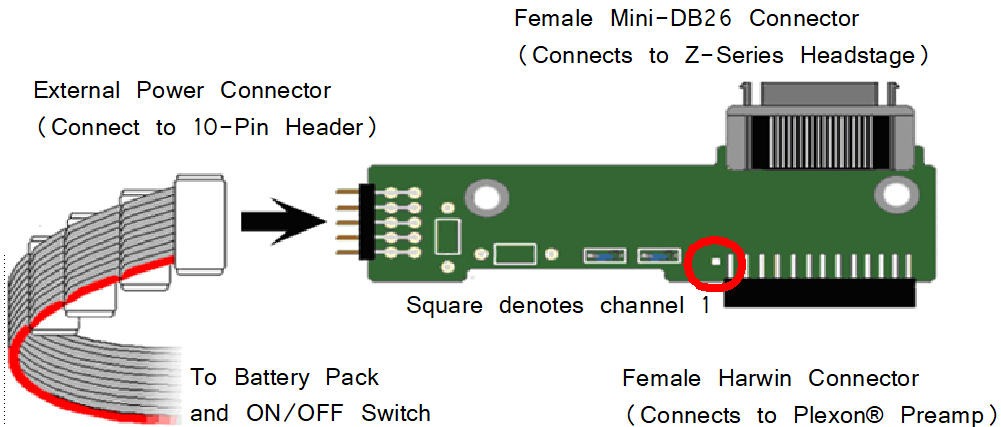 |
| External Power Source Connector and a Single PLX-ZCA Adapter Board |
External Power Source
In order to power TDT headstages when using this adapter, an external power source is required. Each external power source includes four connectors and can power up to four PLX-ZCA adapter boards. The external power source uses two 1.5 V D batteries and is enabled through a simple ON/OFF switch.
To power the PLX-ZCA adapter:
-
Align the red colored stripe to the Harwin connector side of the adapter (as shown in the diagram above).
-
Connect an external power connector to the 10-pin header located on the adapter.
-
Ensure that the batteries are correctly inserted in the battery pack then move the switch to the ON position.
Note
To power multiple PLX-ZCA adapters, simply connect each 10-pin header to one of the available external power connectors.
Plexon Header Pinout
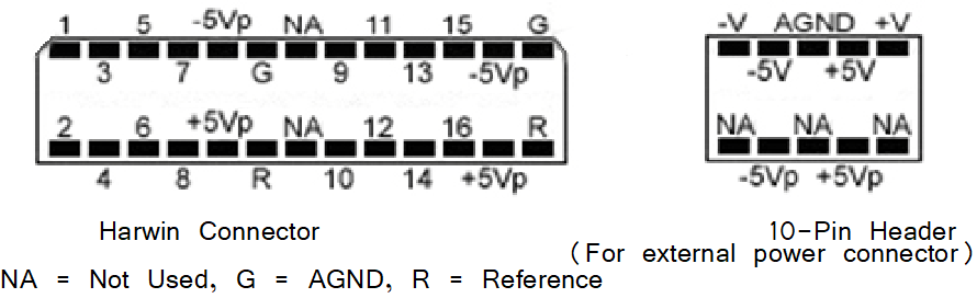 |
| Pinouts are looking into the connector and reflect the preamplifier channels |
SB64 64-Channel Stimulator Buffer
This adapter provides multiple ways of connecting up to 64-channels. Two mini- DB80 connectors, one for direct connection to a PZ5M NeuroDigitizer/Amplifier and one for connection to up to 64 electrode channels. Two DB37 connectors provide an additional passive input or output connection. Each DB37 is tied to the corresponding 32 electrode channels and is buffered from the active electronics associated with the PZ amplifier connection. They can be used to connect stimulation to the corresponding electrodes, pass electrode signals to a parallel recording system, or serve as an alternative input connection from a breakout box (such as a a Xltek EMU128FS).
The SB64 uses standard 1.5 mm safety connectors for Ground and Reference (REF) connections. Front panel numbering of the DB37 connectors corresponds to TDT amplifier channels. Use caution to avoid miswiring.
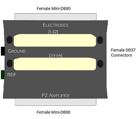
The DB37s connect to stimulator, parallel recording system, or an alternative breakout box.
The Female Mini-DB80 connects to the PZ5M via a Male to Male Ribbon Cable.
Caution
The maximum allowed stim voltage through the SB64 is ±15 V
Pinout Diagrams
(1-32) DB37 Connector
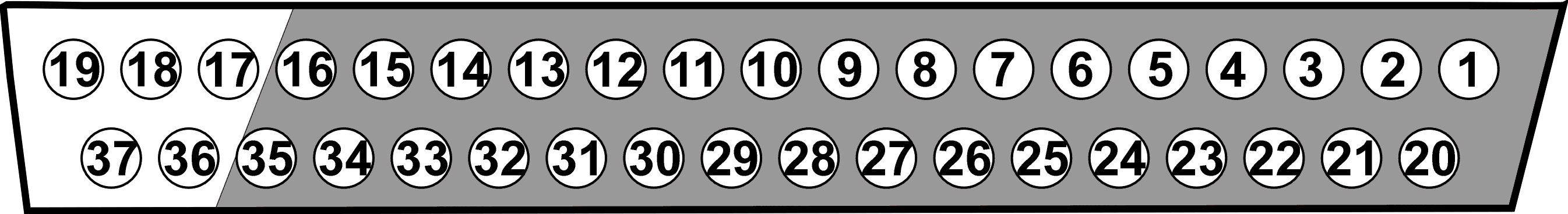
Note
No connections should be made to pins 17, 18, and 36.
(33-64) DB37 Connector
Increment above channel numbers by 32.
Electrodes Mini-DB80
The pinout for this connector duplicates the map of the PZ5M Input Connectors and is dependent on the PZ5M reference mode.