Low Impedance Headstages
RA4LI - Four Channel Headstage
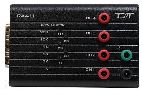
The RA4LI headstage is designed for low impedance electrodes with input impedance between <1 kOhm and 20 kOhm. Electrode connectors are standard 1.5 mm safety connectors making it easy to connect to standard needle and surface electrodes for recording evoked potentials and EEG's. The headstage connects directly to the RA4PA Medusa preamplifier's 25-pin connector. A built-in impedance checker can be used to test each channel and the reference. Additional 20x gain on the headstage improves signal-to-noise of low voltage signals.
Impedance Checking with the Low-Impedance Headstage
The impedance checker on the RA4LI provides a simple check of the channel impedance relative to ground. To check the impedance level, press the button next to the channel indicator. The highest-level light indicates the maximum impedance between the channel and the ground. If all impedance lights are illuminated it is likely that one of the channels is not properly connected. The (-) impedance button checks the impedance between the reference (black connector) and the ground (green connector).
Headstage Voltage Range
When using a TDT preamplifier the voltage input range of the preamplifier (PZ5, Subject Interface, RA16PA) is typically lower than the headstage and must be considered the effective range of the system. Also keep in mind that the output range of the headstage varies depending on the power supply provided by the preamplifier. PZ5 and Subject Interface supply ±2.5 V. PZ2 and RA16PA preamplifiers supply ±1.5 V. Third party preamplifiers may vary. TDT recommends using preamplifiers which deliver ±2.5 V or less. The table below lists the input voltage ranges for the RA4LI headstage for either ±1.5 V or ±2.5 V power sources.
RA4LI Technical Specifications
RA16LI - 16 Channel Headstage
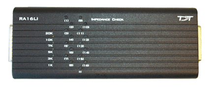
The sixteen channel low impedance headstage (RA16LI) is a high quality, low- impedance headstage designed for recording high channel count EEG's.
The RA16LI headstage is designed for low impedance electrodes and electrode caps with input impedance between <1 kOhm and 20 kOhm. Either headstage unit connects to the Medusa preamplifier's 25-pin connector. The simple interface to the RA16PA preamplifier makes it easy to connect your electrodes to our system.
An adapter is also available to connect a low impedance headstage to a PZ preamplifier. See Preamplifier Adapters for more information. A built-in impedance checker can be used to test each channel and the reference. Additional 20x gain on the headstage improves signal-to-noise of low voltage signals.
Impedance Checking with the Low-Impedance Headstage
The impedance checker on the RA16LI provides a simple check of the channel impedance relative to ground. To check the impedance level, press the button next to the channel indicator. The highest-level light indicates the maximum impedance between the channel and the ground. If all impedance lights are illuminated it is likely that one of the channels is not properly connected. The (-) impedance button checks the impedance between the reference and the ground.
Headstage Voltage Range
When using a TDT preamplifier the voltage input range of the preamplifier (PZ5, Subject Interface, RA16PA) is typically lower than the headstage and must be considered the effective range of the system. Also keep in mind that the output range of the headstage varies depending on the power supply provided by the preamplifier. PZ5 and Subject Interface supply ±2.5 V. PZ2 and RA16PA preamplifiers supply ±1.5 V. Third party preamplifiers may vary. TDT recommends using preamplifiers which deliver ±2.5 V or less. The table below lists the input voltage ranges for the RA16LI headstage for either ±1.5 V or ±2.5 V power sources.
RA16LI Technical Specifications
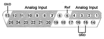
Electrode Connector Pinout
The electrode connector is a 25-pin connector. Information on the pin inputs is provided below.
Note
Pins 6, 14, 17, 18 and 19 are not connected.
RA16LI-D - 16 Channel Headstage with Differential
The RA16LI-D headstage is designed for fully differential recordings from low impedance electrodes and electrode caps with input impedance between <1 kOhm and 20 kOhm. It connects to the Medusa preamplifier's 25-pin connector. The simple interface to the RA16PA preamplifiers makes it easy to connect your electrodes to our system. An adapter is also available to connect a low impedance headstage to a PZ preamplifier. See DBF-MiniDBM Low Impedance Headstage to PZ Preamplifier (16-channels) for more information.
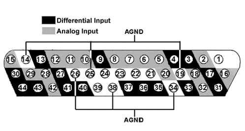
The differential inputs allow for improved common mode rejection on all channels. Because of the increased complexity of the circuitry, the RA16LI-D does not have impedance checking. The headstage connector is a DB44. The pin out diagram is shown below.
Headstage Voltage Range
When using a TDT preamplifier the voltage input range of the preamplifier is typically lower than the headstage and must be considered the effective range of the system. Check the specifications of your amplifier for voltage range.
RA16LI-D Technical Specifications
Pinout Diagram
Note
Pins 1, 21-24 and 39 are not connected.