Acute (Non-ZIF) Headstages
NN32AC - 32 Channel Acute Headstage
The 32 Channel Acute headstage is recommended for extracellular neurophysiology using silicon electrodes, metal microelectrodes or microwire arrays with input impedance from 20 kOhm to 5 Mohm. The headstage features a 40-pin connector designed for use with the NeuroNexus Acute 32-channel probe. The headstage connects to a PZ series preamplifier via two mini 26-pin connectors or to two RA16PA preamplifiers via two 25-pin connectors. For either headstage, Connector A carries the signals for channels 1-16, power and ground. This connector must be connected whether you are acquiring data from one of these channels or not.
Part Numbers:
NN32AC - 32-Channel Acute Headstage for Medusa PreAmps
NN32AC-Z - 32-Channel Acute Headstage for PZ PreAmps
Warning
The headstage has sensitive electronics. Always ground yourself before handling.
Headstage Voltage Range
When using a TDT preamplifier the voltage input range of the preamplifier (PZ5, Subject Interface, RA16PA) is typically lower than the headstage and must be considered the effective range of the system. Also keep in mind that the output range of the headstage varies depending on the power supply provided by the preamplifier. PZ5 and Subject Interface supply ±2.5 V. PZ2 and RA16PA preamplifiers supply ±1.5 V. Third party preamplifiers may vary. TDT recommends using preamplifiers which deliver ±2.5 V or less. The table below lists the input voltage ranges for the NN32AC and NN32AC-Z headstages for either ±1.5 V or ±2.5 V power sources.
Jumper Configuration
The following table describes the jumper configurations and associated requirements.
Technical Specifications
Pinout
Important
When using the NN32AC with the NeuroNexus Acute 32-channel probe, keep in mind that there are several versions of the probe and the NN32AC was designed to correspond to the NeuroNexus rev 3 probe. Check the NeuroNexus Website for pin diagrams. For Synapse users, use the Channel Mapper gizmo to reorder the channels according to the pinouts below.
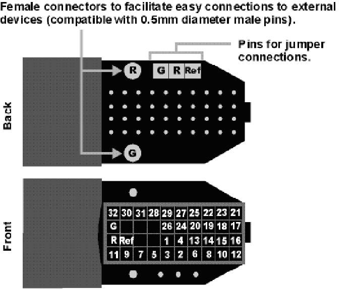 |
| Pinouts are looking into the connector and reflect the preamplifier channels |
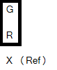
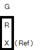
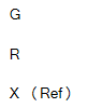
The surfaced connections on the back of the headstage include female connectors to simplify connections to external devices and jumper locations to short G, R and Ref refers to the built-in reference site on the NeuroNexus probe). The ground channel (G) should either be tied to an external ground or to the reference (R) for a single ended input.
Important
When using multiple headstages, ensure that a single ground is used for all headstages. This will avoid unnecessary noise contamination in recordings. See the Headstage Connection Guide for more information.
NN64AC 64-Channel Acute Headstage
The 16 Channel acute The 64 Channel Acute headstage is recommended for extracellular neurophysiology using silicon electrodes, metal microelectrodes or microwire arrays with input impedance from 20 kOhm to 5 Mohm.
The headstage features two 40-pin connectors designed for use with NeuroNexus Acute 64-channel probes. The headstage connects to a PZ series preamplifier via four mini 26-pin connectors or with System 3 Medusa preamplifiers (such as four RA16PAs) via four DB25 connectors. In either case, each connector carries the signals for 16 channels, power and ground. Therefore, each connector can be connected independently. The connector labeled Bank-1 carries channels 1-16, Bank-2 carries 17-32, etc.
Part Numbers:
NN64AC - 64-Channel Acute Headstage for Medusa PreAmps
NN64AC-Z - 64-Channel Acute Headstage for PZ PreAmps
Warning
The headstage has sensitive electronics. Always ground yourself before handling.
Headstage Voltage Range
When using a TDT preamplifier the voltage input range of the preamplifier (PZ5, Subject Interface, RA16PA) is typically lower than the headstage and must be considered the effective range of the system. Also keep in mind that the output range of the headstage varies depending on the power supply provided by the preamplifier. PZ5 and Subject Interface supply ±2.5 V. PZ2 and RA16PA preamplifiers supply ±1.5 V. Third party preamplifiers may vary. TDT recommends using preamplifiers which deliver ±2.5 V or less. The table below lists the input voltage ranges for the NN64AC-Z headstage for either ±1.5 V or ±2.5 V power sources.
Jumper Configuration
The following table describes the jumper configurations and associated requirements.
Technical Specifications
Pinout
Important
When using the NN64AC with the NeuroNexus Acute 64-channel probe, keep in mind that there are several versions of the probe. Check the NeuroNexus Website for pin diagrams. For Synapse users, use the Channel Mapper gizmo to reorder the channels according to the pinouts below.
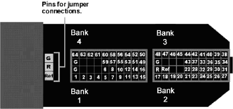 |
| Pinouts are looking into the connector and reflect the preamplifier channels |
The numbers in the diagram above show the channel connections to the amplifier. The headstage also features jumper locations to short G, R and Ref refers to the built-in reference site on the NeuroNexus probe). The ground channel (G) should either be tied to an external ground or to the reference (R) for a single ended input.
Important
When using multiple headstages, ensure that a single ground is used for all headstages. This will avoid unnecessary noise contamination in recordings. See the Headstage Connection Guide for more information.
RA16AC - 16 Channel Acute Headstage
The 16 Channel acute headstages is recommended for extracellular neurophysiology using silicon electrodes, metal microelectrodes or microwire arrays with recommended input impedance from 20 kOhm to 5 Mohm unless otherwise noted.
The 16 channel acute headstage has an 18-pin DIP connector that can be used with standard high impedance metal electrodes. The pinout of the RA16AC matches the wiring of NeuroNexus electrodes to allow for direct connection to the headstage. TDT recommends connecting electrodes to an 18-pin socket and then connecting the socket to the headstage to protect the headstage from unnecessary wear and tear. The RA16AC4 provides 4x gain and is used with electrodes with a recommended impedance range of 20 kOhm to 300 kOhm.
The headstage connects to a System 3 Medusa preamplifier (such as the RA16PA) via a DB25 connector or to a PZ series preamplifier via a mini 26-pin connector.
Part Numbers:
RA16AC - 16-Channel Acute Headstage for Medusa PreAmps, with unity (1x) gain
RA16AC4 - 16-Channel Acute Headstage for Medusa PreAmps, with 4x gain
RA16AC-Z - 16-Channel Acute Headstage for PZ PreAmps, with unity (1x) gain
Warning
The headstage has sensitive electronics. Always ground yourself before handling.
Headstage Voltage Range
When using a TDT preamplifier the voltage input range of the preamplifier (PZ5, Subject Interface, RA16PA) is typically lower than the headstage and must be considered the effective range of the system. Also keep in mind that the output range of the headstage varies depending on the power supply provided by the preamplifier. PZ5 and Subject Interface supply ±2.5 V. PZ2 and RA16PA preamplifiers supply ±1.5 V. Third party preamplifiers may vary. TDT recommends using preamplifiers which deliver ±2.5 V or less. The table below lists the input voltage ranges for the RA16AC and RA16AC4 headstages for either ±1.5 V or ±2.5 V power sources.
Technical Specifications
Pinout
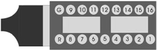 |
| Pinouts are looking into the connector and reflect the preamplifier channels |
The electrode connector accepts 0.5 mm diameter male pins. For pinouts for the preamplifier connector, see the RA16PA pinout.
Important
When using multiple headstages, ensure that a single ground is used for all headstages. This will avoid unnecessary noise contamination in recordings. See the Headstage Connection Guide for more information.
RA4AC - 4 Channel Acute Headstage
The 4 Channel Acute headstages are recommended for extracellular neurophysiology using silicon electrodes, metal microelectrodes, or microwire arrays with input impedance from 20 kOhm to 5 MOhm.
The RA4AC1 and RA4AC4 headstages have a low-profile 6-pin connector. The RA4AC1 provides unity gain (1x). The RA4AC4 provides 4x gain and is used with electrodes with a recommended impedance range of 20 kOhm to 300 kOhm. The 25-pin connector connects to the RA4PA 4-channel Medusa preamplifier.
Part Numbers:
RA4AC1 - 4-Channel Acute Headstage for Medusa PreAmps, with unity (1x) gain
RA4AC4 - 4-Channel Acute Headstage for Medusa PreAmps, with 4x gain
Warning
The headstage has sensitive electronics. Always ground yourself before handling.
Headstage Voltage Range
When using a TDT preamplifier the voltage input range of the preamplifier (PZ5, Subject Interface, RA16PA) is typically lower than the headstage and must be considered the effective range of the system. Also keep in mind that the output range of the headstage varies depending on the power supply provided by the preamplifier. PZ5 and Subject Interface supply ±2.5 V. PZ2 and RA16PA preamplifiers supply ±1.5 V. Third party preamplifiers may vary. TDT recommends using preamplifiers which deliver ±2.5 V or less. The table below lists the input voltage ranges for the RA4AC and RA4AC4 headstages for either ±1.5 V or ±2.5 V power sources.
Technical Specifications
Pinout
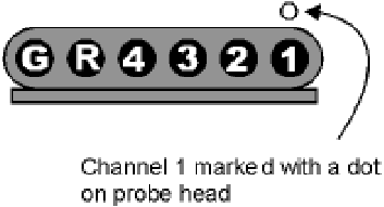 |
| Pinouts are looking into the connector and reflect the preamplifier channels |
The electrode connector accepts 0.76 mm diameter male pins. For pinouts for the preamplifier connector, see the RA16PA pinout.
Important
When using multiple headstages, ensure that a single ground is used for all headstages. This will avoid unnecessary noise contamination in recordings. See the Headstage Connection Guide for more information.
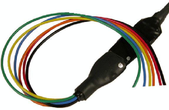
The RA4AC1/RA4AC4 also comes with a 6-pin male connector with flying leads. When connecting to the headstage, note that the silver dots marking channel 1 line up.
The colors of the lead wires correspond to the headstage channels as follows: