ZIF-Clip® Headstage Holders
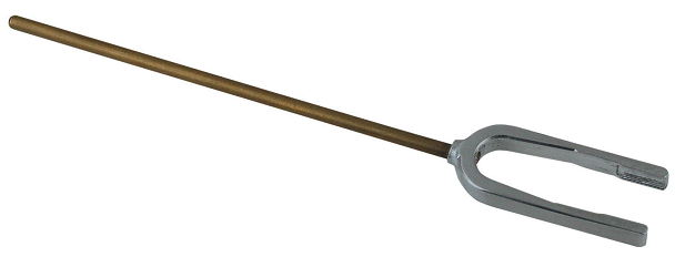
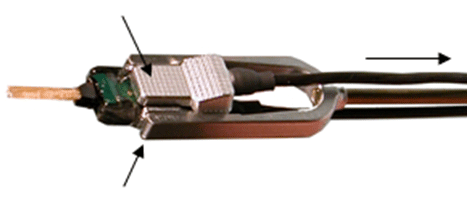
The ZIF-Clip® headstage holders securely hold your analog or digital ZIF-Clip® headstages during electrode insertion and can be used with most micromanipulators. The headstage holders, including the stabilizing rod, are approximately 4.5" in length. The stabilizing rod is 3" in length and has a 3/32" diameter. An aluminum lock pin ensures the ZIF-Clip® does not open during insertion.
Each holder is designed for use with the corresponding ZIF-Clip® or Digital ZIF-Clip® headstage.
Part Numbers:
Z-ROD32 - 16 or 32-channel analog ZIF-Clip® headstage holder (for ZC32)
Z-ROD64 - 64-channel analog ZIF-Clip® headstage holder (for ZC64 and ZD64)
Z-ROD96 - 96-channel analog ZIF-Clip® headstage holder (for ZC96 and ZD96)
Z-ROD128 - 128-channel analog ZIF-Clip® headstage holder (for ZC128)
ZCD-ROD32 - 32-channel digital ZIF-Clip® headstage holder (for ZCD32 and ZD32)
ZCD-ROD64 - 64-channel digital ZIF-Clip® headstage holder (for ZCD64)
ZCD-ROD96 - 96-channel digital ZIF-Clip® headstage holder (for ZCD96)
Using the Holder with ZIF-Clip® Headstages
Each holder is sized to fit a particular headstage and with the exception of the ZCD-ROD32 (see below), they all can be fitted to the headstage in the same way.
First, connect the probe or adapter to your ZIF-Clip® headstage before putting the headstage in the holder (the square guide provided to ensure the probe or adapter is connected with the correct polarity is hidden from view when the headstage is in the holder). See ZIF-Clip® Headstage Adapters for more information.
Next, gently slide the ZIF-Clip® headstage onto the holder until it is completely secure as shown in the images below.
Finally, secure the lock pin to the headstage holder.
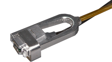
Using the ZCD-ROD32
The ZCD-ROD32 has a unique design that requires a different insertion procedure.
To use the headstage holder:
-
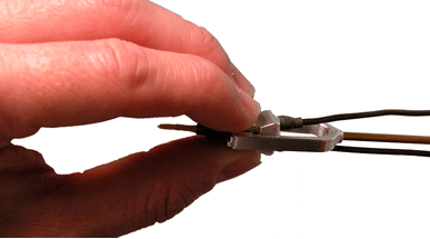
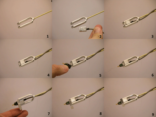
Set the ZCD32 headstage inside the base (or U) of the holder and slide it forward until it is stopped by the interior flange (Image 1-4).
-
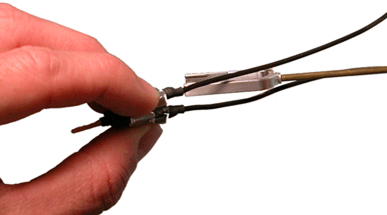
After the clip is in place, insert the probe (Image 5-6) and then slide the provided lock pin over the ZCD32 (Image 7-9).
The lock pin prevents the clip from opening and releasing the probe, and also from sliding backward during insertion.
The lock pin has small ridges that should be aligned with the grooves on the face of the clip. If you have trouble connecting the lock pin, make sure that the clip has been pushed in completely and that the ridges and grooves are properly aligned (Image 7).
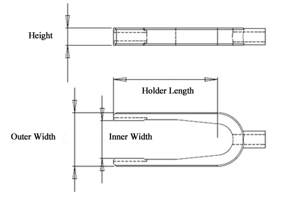
Holder Dimensions