ZB1PS Powered zBUS Device Chassis
Overview
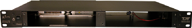
zBUS is TDT's high-speed, low-noise bus for System 3 modules. The bus is integrated into a device chassis, which serves as a rack mountable housing for most modular devices in the System 3 line, excluding the RZ processors which have their own built-in power supply and computer interface.
As shown in the functional diagram below, the bus distributes communication and power throughout the system.
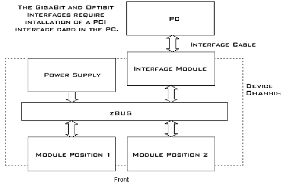 |
| zBUS Functional Diagram |
One or two modular devices can be mounted in the chassis' front bays, providing easy access to front panel connections. An interface module can be mounted in the second rear bay for chassis housing a programmable device. Multiple chassis can be interfaced for custom system configurations and individual modules can be added or removed as needed.
Power Supply
The ZB1PS chassis features an onboard, switchable (115 V / 220 V) power source. The power supply is integrated into the chassis and cannot be removed. A small fan is located inside of the power supply and provides cooling while the power supply is active.
See the ZBPS1 Operations Manual for power and safety information.
Using the ZB1PS
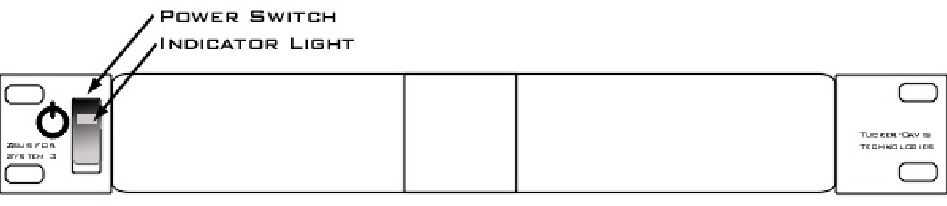 |
| Front View |
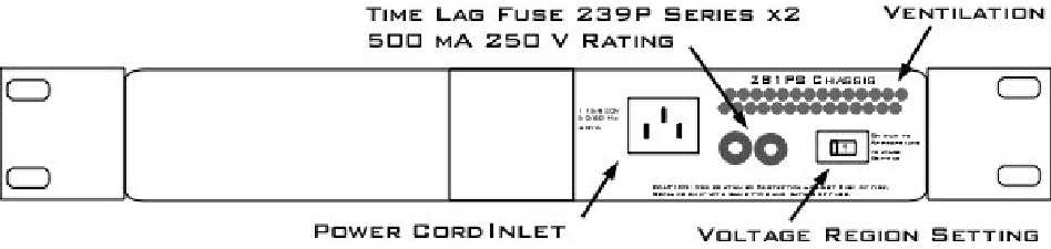 |
| Back View |
Applying Power to the Chassis
Caution
Allow at least 2 cm clearance from each side of the chassis for proper cooling. A ventilation fan is provided on the right side of the chassis. Ventilation holes are also provided on the power supply panel and another internal fan is provided inside the power supply housing. Installation of the chassis with the ventilation obstructed may cause a malfunction or fire.
Caution
Use only the supplied power cord.
To turn the ZB1PS on:
-
Position the chassis so that both the power switch and power cord may be accessed easily.
-
Ensure that the power switch is off then connect the power cord.
-
Ensure that the voltage region switch is set correctly. For standard outlets in the United States it should be switched to 115 V.
-
Turn the power switch on. The power switch's green LED should be illuminated.
The Indicator Light
A front panel switch turns on the chassis power supply and includes an indicator light. The power switch's green LED will illuminate when the chassis is switched on. The light will flash rapidly when it receives a command from software and slowly to indicate a communications error (check all cable connections).
Disconnecting Power from the Chassis
Caution
When removing the power cord from either the power supply or socket outlet, grasp the plug, not the cord, in order to avoid damaging the cable.
To disconnect the ZB1PS:
-
Turn off the power switch.
-
Disconnect the power cord from the power supply.
-
Disconnect the power cord from the wall socket plug.
Adding and Removing Modules
Before adding or removing modules, make sure the ZB1PS is powered off.
To remove a module from the chassis:
-
Unscrew the two thumb screws on the corner of the module faceplate.
-
Pull straight out on the front-panel BNC connectors. A BNC 'T' connector makes a great handle for removing zBUS devices.
To add a module to a chassis:
-
Insert the module into an empty bay and push straight back until it seats onto the connector.
-
Hold the module in place with the thumb screws.