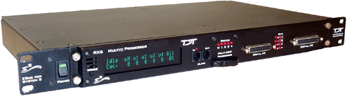
RX8 Multi I/O Processor
RX8 Overview
The RX8 is a high channel count, high sample rate analog I/O system which provides a maximum of 24 channels of analog I/O and generates a maximum sampling rate of 100 kHz per channel. Each bank of four or eight channels of I/O is user configurable with either PCM or sigma-delta converters. The 24-bit sigma-delta converters are ideal for audio applications. The 16-bit PCM analog converters have an excellent dynamic range and almost no group delay. These converters are excellent for acquiring signal information and controlling external devices, such as motors.
The RX8 is equipped with either two or five 100 MHz, 1600 MFLOPS Sharc DSPs and can control audio feedback systems or motor controls in real-time. Built in digital filters, waveform generators, and logic control components give end users the ability to design and control virtually any presentation system.
Power and Communication
The RX8 mounts in a System 3 zBus Powered Device Chassis (ZB1PS) and communicates with the PC using the Optibit (PO5/FO5) PC interface. The ZB1PS is UL compliant, see the ZB1PS Operations Manual for power and safety information.
Software Control
Software control is implemented with circuit files developed using TDT's RP Visual Design Studio (RPvdsEx). Circuits are loaded to the processor through TDT run-time applications or custom applications. This manual includes device specific information needed during circuit design. For circuit design techniques and a complete reference of the RPvdsEx circuit components, see the RPvdsEx Manual.
RX Architecture
Each RX multiprocessor device is equipped with either two or five digital signal processors (DSPs). The multi-DSP architecture allows processing tasks to be distributed across multiple processors and enables data to be transferred to the PC quickly and efficiently. The DSPs include one master and one or four auxiliary DSP(s). 128 MB SDRAM of system memory is shared by all DSPs. When designing circuits the maximum number of components for each RX DSP is 256.
Each DSP communicates with an internal bus to send and receive information from the I/O controller and the shared memory. The master DSP supervises overall system boot up and operation. The master DSP also acts as the main data interface between the zBus (host PC) and the multi-DSP environment.
Because the zBus communicates only with the master processor, these devices operate most efficiently when the circuit related processing tasks assigned to the master DSP are minimized, allowing more processor power (cycles) for communication and overhead tasks.
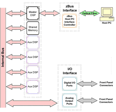
The RX8 contains two DB25 connectors for interfacing with 24 bits of digital I/O and 24 channels of analog I/O.
Distributing Data Across DSPs
In RPvdsEx data can be transferred between each of the auxiliary DSPs as well as the master DSP using zHop components.
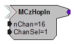
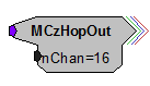


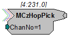
Components such as MCzHopIn and MCzHopOut can be used for multi-channel signals while components such as zHopIn, zHopOut, and MCzHopPick are used with single- channel signals. Up to 126 pairs can be used in a single RPvdsEx circuit.
Bus Related Delays
The zHop Bus introduces a single sample delay. However, this delay is taken care of for the user in OpenEx when Timing and Data Saving macros are used.
See "MultiProcessor Circuit Design" in the RPvdsEx Manual for these and other multiprocessor circuit design techniques.
RX8 Features
DSP Status Displays
All high performance RX multiprocessors include status lights and a display screen to report the status of the individual processors.
Status Lights
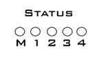
Up to five LEDs report the status of the multiprocessor's individual DSPs. When the device is turned on, they will glow steadily. If the demands on a DSP exceed 99% of its capacity on any given cycle, the corresponding LED will flash very rapidly (~3 times per second).
Front Panel Display Screen
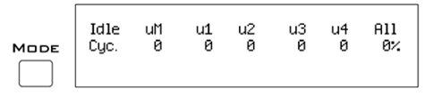
The front panel display screen reports detailed information about the status of the system. The display includes two lines. The top line reports the system mode, Run! or Idle, and displays heading labels for the second line. The second line reports the user's choice of status indicators for each DSP followed by an aggregate value.
The user can cycle through the various status indicators using the Mode button to the left of the display. Push and release the button to change the display or push and hold the button for one second then release to automatically cycle through each of the display options. The display screen may also report system status such as booting status (Booting DSP) or alert the user when the device's microcode needs to be reprogrammed (Firmware Blank).
Status Indicators
Important
The status lights will flash (~3 times a second) to alert the user when a device goes over the cycle usage limit, even if only for a particular cycle. This helps to identify periodic overages caused by components in time slices.
Bits Lights
The RX8's eight Bits lights are user configurable. By default the Bits lights indicate the logic level (lit when high) for the eight bit-addressable digital I/O lines. The Bits lights can also act as logic level lights for any of the other bytes of digital I/O.
Analog Input/Output
The RX8 can have a maximum of 24 channels of analog I/O accessed via the 25-pin connector on the front panel. Each bank of up to eight channels of I/O is user configurable with either PCM or sigma-delta converters.
Sigma-delta converters provide superior conversion quality and extended useful bandwidths, at the cost of an inherent fixed group delay. When equipped with sigma-delta, the RX8 DAC Delay is 23 samples and the RX8 ADC Delay is 47 samples.
This device can sample at rates up to ~100 kHz. For additional information on sampling rates for both PCM and sigma-delta converters, see Realizable Sampling Rates for the RX8.
Important
Because of device timing constraints at higher sampling rates, only the first 23 channels of analog I/O are processed when operating the RX8 at ~100 kHz.
The analog I/O of each device is custom configured at the factory. Problems will arise if end users do not carefully note the configuration of their RX8 device. This topic provides information about configurations and channel numbering. The RX8's analog I/O channels are accessed via a 25-pin connector on the front panel. If you know what channel numbers your device uses, See RX8 Technical Specifications or the Analog I/O pinout diagram.
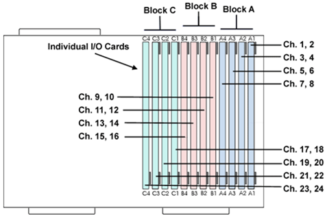
Organization of Analog I/O Blocks
The RX8 has three blocks of I/O ports. Each block can house up to eight channels for a total of 24 channels of analog I/O. Blocks can only be filled by analog I/O modules of the same type.
For example:
A block can be configured with all D/A's or all A/D's, but not a mixture of D/A's and A/D's. In addition, the D/A's and A/D's must be of the same type (either PCM or sigma-delta).
Note
Block C can only be configured with D/A output channels
Channel Numbers
Starting with block A and ending with block C, channels are numbered sequentially from 1 to 24. The channel numbering is independent of whether the analog I/O board is an input or output.
For example:
The analog I/O of an RX8 that has four A/D's in the first two slots of Block A and four D/A's in the first two slots of Bank C, would be accessed with the A/D's as channels 1-4 and the D/A's as channels 17-20.
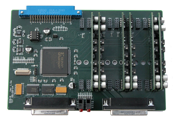
The photo below shows one possible configuration of the RX8's I/O boards. This configuration uses channels 1-4, 9-12, and 17-20.
Digital I/O
The RX8 processor includes 24 bits of programmable I/O in two eight bit word- addressable bytes and eight bits of bit-addressable I/O. Digital I/O lines are accessed via the 25-pin connector on the front panel and can be configured as inputs or outputs. See the "Digital I/O Circuit Design" section of the RPvdsEx Manual for more information on programming the digital I/O.
Caution
The first eight bits of bit-addressable digital I/O on RX devices are unbuffered. When used as inputs, overvoltages on these lines can cause severe damage to the system. Never send a signal with amplitude greater than five volts into any digital input.
Configuring the Programmable I/O Lines
Each of the eight bit-addressable bits can be independently configured as inputs or outputs. The digital I/O lines can be configured as inputs or outputs in groups of eight bits - that is as byte A and byte B. Note, however, that the bytes must be addressed as if part of a word, not as individual bytes. See "Addressing Digital Bits In A Word" in the RPvdsEx Manual for more information.
By default, all bits are configured as inputs. This default setting is intended to prevent damage to equipment that might be connected to the digital I/O lines. The user can configure the bits in the RPvdsEx configuration register. The configuration register is also used to determine what the eight front panel Bits lights represent.
To access the bit configuration register:
-
Click the Device Setup command on the Implement menu.
-
In the Set Hardware Parameters dialog box, click the Device Type box and select RX8 Multi-Chan I/O from the list.
The dialog expands to display the Device Configuration Register.
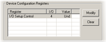
-
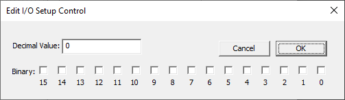
Click Modify to display the Edit I/O Setup Control dialog box.
In this dialog box, a series of check boxes are used to create a bitmask that is used to program all bits.
-
To determine the desired value, select or clear the check boxes according to the table below. By default, all check boxes are cleared (value = 0). Selecting a check box sets the corresponding bit in the bitmask to one.
-
When the configuration is complete, click OK to return to the Set Hardware Parameters dialog box.
Bit Codes for Controlling the Bit Lights (Boxes 12-14)
By default, check boxes 12 -14 in the Edit I/O Setup Control dialog box (previous diagram) are cleared to create the bit code 000. This configures the eight front panel Bits lights to act as activity lights (glow when high) for the eight bit addressable digital I/O lines. The Bits lights can also be configured to provide information about amplifier status or act as activity lights for any of the other four bytes of digital I/O.


XLink
The XLink is not supported at this time.
Realizable Sampling Rates for the RX8
PCM converters support a broad range of sampling rates up to the maximum of ~100 kHz. Realizable sampling rates can easily be determined in the device set-up dialog in RPvdsEx.
Sigma-Delta converters support a more limited set of sampling rates as shown in the table below. When using Sigma-Delta converters, the user must ensure a valid sampling rate is set for the device.
Note
The Check Realizable button in the device set-up dialog in RPvdsEx is used to calculate the true sampling rate of the system when an arbitrary sampling rate is used. This rate is based on the PCM converters. If your RX8 contains any sigma-delta converters you must use the following values for arbitrary sampling rates.
Supported Arbitrary Sample Rates for Sigma-Delta Converters
RX8 Technical Specifications
* Because of device timing constraints at higher sampling rates, only the first 23 channels of analog I/O are processed when operating the RX8 at 100 kHz. See Realizable Sampling Rates for the RX8 for a list of supported sampling rates.
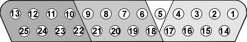
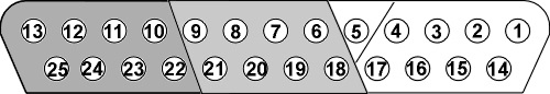
DB25 Connector Pinouts
TDT Recommends accessing the RX8 I/O via a PP24 patch panel.
Analog I/O
Digital I/O