MZ60 MicroElectrode Array Interface
MZ60 Overview
The MZ60 Microelectrode Array (MEA) Interface is used with our RZ2 BioAmp Processor and the PZ5 NeuroDigitizer (or SIM Subject Interface) as part of a complete solution for high spatio-temporal resolution tissue slice and cell culture recordings.
The interface supports simultaneous stimulation and extracellular in-vitro recording on up to 60 channels. Headstage buffering on the MZ60 provides high signal-to-noise ratio, sensitivity, and stability for long experimental durations.
The MZ60 is compatible with a large selection of MEA plates and both inverted and upright microscopes.
The MEA System
A typical system consists of an RZ2 processor, a PZ5 digitizer and the MZ60 MEA interface. An optional stimulus generation device may also be used and controlled by the RZ2 processor as part of an integrated solution. The diagram below illustrates the function of the components in the system.
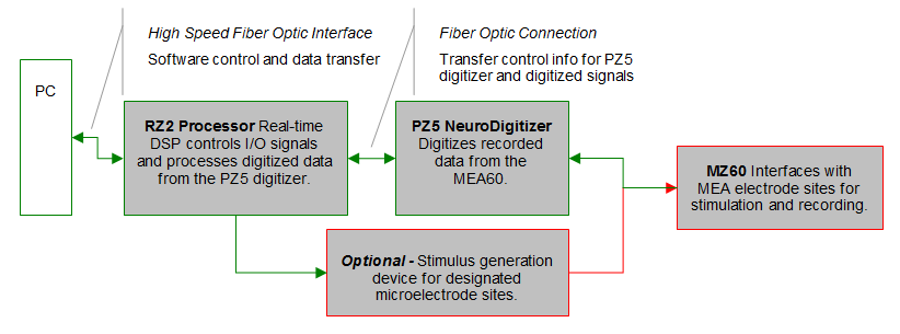 |
| MEA System Diagram |
The MZ60 acquires analog input signals from cell lines or tissue slices via an MEA plate and sends those signals to the PZ5 digitizer. All channels are digitized on the PZ5 at up to ~50 kHz sampling rate per channel. Digitized data is streamed to the RZ2 multiprocessor DSPs on a fiber optic connection and processed data is transferred to the PC for data storage. A single RZ2 and PZ5 system is capable of interfacing with up to two MZ60's.
Stimulation can be delivered to any of the MZ60's electrode sites while the RZ2 processor simultaneously records from non-stimulus channels and may be provided by the RZ2 processor or an optional stimulus device.
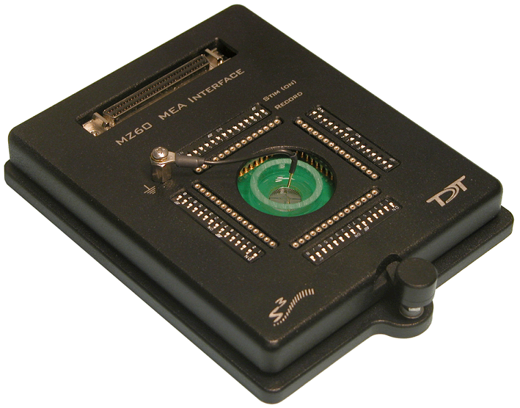
The MEA Interface
The MZ60 is compatible with the standard 49 x 49 mm arrays from NMI or Ayanda Biosystems and can accommodate a wide selection of readily available arrays. The arrays are placed on an aluminum plate and spring loaded connections are secured over the contact pads when the top is lowered and locked using the twist lock mechanism.
A voltage-follower headstage provides a high input impedance and low output impedance with unity-gain. The dynamic range of the MZ60 and PZ5 is 500 mV with a signal resolution of 3 uVolt or less at ~25 kHz sampling rate.
The MZ60 channels are organized in four individual 16-channel banks that correspond to banks of channels on the PZ5 digitizer. Each bank transmits 15 analog signals recorded from the MEA to the PZ5 digitizer (the sixteenth channel of each bank is connected to ground and is not used). If any channel is designated for stimulation, it is grounded internally on the PZ5.
Headstage Voltage Range
When using a TDT preamplifier the voltage input range of the preamplifier (PZ5, Subject Interface, RA16PA) is typically lower than the headstage and must be considered the effective range of the system. Also keep in mind that the output range of the headstage varies depending on the power supply provided by the preamplifier. PZ5 and Subject Interface supply ±2.5 V. PZ2 and RA16PA preamplifiers supply ±1.5 V. Third party preamplifiers may vary. TDT recommends using preamplifiers which deliver ±2.5 V or less. The table below lists the input voltage ranges for the MZ60 headstage for either ±1.5 V or ±2.5 V power sources.
Hardware Set-up
To insert the MEA into the MZ60:
-
Twist the knob on the front edge of the MZ60 counterclockwise to release the hinged top.
-
Lift the top and position the MEA on the aluminum plate.
-
Lower the top and twist the knob clockwise to secure the MEA inside the interface housing.
Important
The securing knob on the MEA turns on a screw that allows for pressure adjustment between the MEA plate and the MZ60 interface contact pins. The pressure should be set to achieve only light contact between the spring loaded contact pins and the MEA plate (enough pressure to visually depress the spring contacts). Excessive pressure may cause damage to the device or MEA plate.
Refer to the vendor's specifications of the chosen MEA plate regarding the MEA pinouts and technical specifications of the electrodes.
To connect the system hardware:
-
Ensure that the TDT drivers, PC interface, and device chassis are installed, setup, and configured according to the System 3 Installation Guide provided with your system.
-
Connect the MZ60 Interface to the PZ5 digitizer via the MZ60 interface cable provided. Attach the 68-pin D-Sub connector on the interface cable to the corresponding connector on the MZ60.
-
Attach each of the labeled Mini-DB26 connectors to the corresponding channel bank connector on the PZ5 digitizer.
-
Connect the PZ5 digitizer to the RZ2 processor using the provided fiber optic cable. The fiber optic wires are keyed and color coded to reduce connection errors.
-
Power on the RZ2 processor and PZ5 digitizer.
-
If using the system with other devices, such as a third party stimulus device or preamplifiers, see the documentation for those devices for hardware connection information.
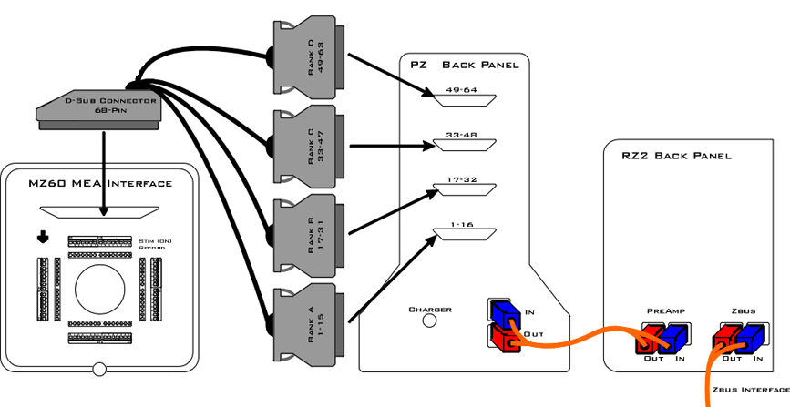 |
| Setup of the MEA System |
MEA Interface Features
Analog Input and Output
The MZ60 supports MEAs containing up to 60 electrode sites. Any of these analog channels may be configured for recording or stimulus presentation using top panel stimulus switches.
Stimulus Switches
A DIP-style switch for each of the 60 analog input channels controls whether the channel is in Stimulate mode ( ON ) or Record mode ( OFF ).
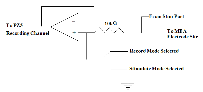 |
| MZ60 Single Channel Circuit Diagram |
Each of the sixty channels can be configured in one of two states:
Warning
Channels designated for recording are still connected to the corresponding stim port located on the MZ60. To avoid damage to the MZ60 headstage, DO NOT attempt to present stimulus signals to channels configured for record mode.
MZ60 Interface Cable Connector
An interface cable is provided to connect the MZ60 to the PZ5 digitizer. The cable features four mini-DB26 connectors which connect to four banks on the back of the PZ5.
Common Ground Pin
A single ground pin is attached to the MZ60 and serves as the common ground for both stimulating and recording channels on the MZ60. The PZ5 digitizer ground and reference pins for each bank are tied to this pin internally when the PZ5 and MZ60 are connected.
Some MEA plates have an internal reference pin integrated into dish. Please review the MEA dish manufacturer specifications for proper grounding.
Troubleshooting
This section is provided to address common issues that may be encountered when using the MZ60 MEA Interface. If you need assistance beyond the scope of this guide, contact tech support at +1.386.462.9622 or support@tdt.com.
General Tips
When recording signals make sure that the PZ5 digitizer is not connected to the charger as this will induce mains interference in your recordings.
Make sure there are no power strips or AC power sources anywhere near the MZ60 setup. Power strips will induce mains interference into your recordings. Also minimize electrical interference from other electrical devices (50-60 Hz and their harmonics). We recommend that the MZ60 and PZ5 are approximately 1 meter from computers, oscilloscopes, RZ and RX devices and other electronic equipment.
Make sure there is no liquid on the MEA plate contacts. Clean the contacts gently with isopropyl alcohol to assure a clean connection.
Make sure the MZ60 knob is oriented in the correct position. If the MZ60 top is not tight enough, open the MZ60 and ensure that the MEA plate is seated correctly in the MZ60 housing. As you close the MZ60 top ensure that all of the gold pins are touching the MEA electrode dish contacts.
Make sure that all of the spring-loaded contact pins are not stuck in a compressed position. If a pin becomes stuck, use a pair of forceps or small pliers to gently pull the pin out.
MZ60 Noise Floor is Too High
If 50-60 Hz hum (caused by mains voltage sources) is prevalent in your recordings, make sure that the common ground wire is making contact with the liquid in the MEA.
Noisy Single Electrode Channels
Large noise signals may be a sign of a bad electrode contact or pin. To test the electrode contact, rotate the MEA plate and see if the noise follows the MZ60 channel or the electrode.
If the electrode contact is affected you may remedy the problem by cleaning the MEA contact sites with a cotton swab and some pure alcohol (100%). If the problem persists after cleaning the MEA electrode contacts, the contacts are damaged beyond repair and the MEA plate must then be replaced.
MZ60 Technical Specifications
MEA Connector Pinouts
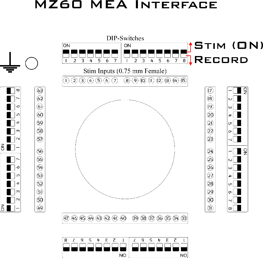 |
| Stimulate/Record Switching Banks |
A DIP-switch bank is located on each of the four sides of the MZ60 and toggles between stimulate or record modes for 15 electrode sites. Stimulating inputs accept 0.75 mm male pins.
Pinouts are shown looking into the connector and reflect the digitizer channels assuming the MZ60 is used with a PZ5-64 or PZA Subject Interface in Local, None, or Shared reference mode. For higher channel count channel numbers may be offset depending on the MZ60-PZ5 connections.
Note
Channels 16, 32, 48, and 64 are grounded on the digitizer.