IZ2M/IZ2MH Medically Isolated Stimulator
IZ2M/IZ2MH Overview
As part of a computer-controlled neural stimulator system, the IZ2M/IZ2MH outputs constant-current stimulation across multichannel electrodes and provides feedback of actual voltages delivered to the electrode. The stimulator converts user-defined digital waveforms to analog current and provides high precision electrical stimulus control. With up to 64 channels, the IZ2MH delivers a maximum of 3 mAmps (300 uAmps for the IZ2M) of current per electrode up to 12 V on up to ten electrodes simultaneously. The device is battery operated with alternative Mains power, used primarily for charging. Full medical grade isolation between the mains power and the electrode outputs ensures electrical isolation, and additional safety features ensure safe operation at all times.
Stimulation
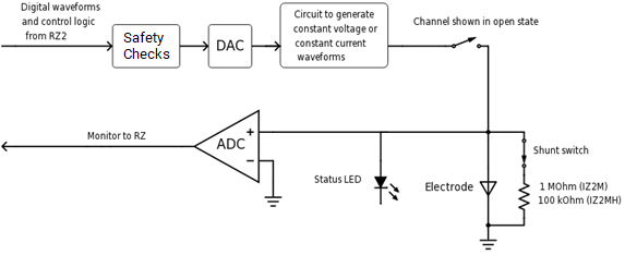
The stimulator can deliver arbitrary waveforms at up to 50 kHz sampling rate. Each channel uses PCM D/As to ensure sample delays of only 4 samples and square edges on pulse stimulation waveforms. Stimulation control waveforms for each electrode channel are first defined on the RZ base station and digitally transmitted to the stimulator. Special circuitry on the stimulator converts voltage waveforms from the D/A converters to constant current waveforms as shown in the diagram below.
 |
| Stimulator Diagram |
The driving voltage is adjusted according to Ohm's law (V=IR), where I is the desired stimulation current and R is the electrode impedance. Eight analog-to- digital (A/D) converters read the output voltage and send that information back to the RZ for monitoring.
Individual channels can be open circuited. A shunt resistor to ground can be applied to all channels (100 kOhm for IZ2MH and 1 MOhm for the IZ2M). This is most useful for electrodes with very high impedance at DC that would normally produce large quiescent DC voltages.
Safety
The IZ2M/IZ2MH's robust safety profile includes both software and hardware components. Control software ensures that the device always boots in safe-mode, meaning all channels power up by default with their relays open. The relays are kept open until the device finishes booting, passes all internal safety checks, and is armed by the user. This ensures absolutely zero current can flow until proper software control is established. During operation, control software ensures that no more than 10 of the channels can be enabled for stimulation at the same time and that maximum output current is not exceeded.
At the hardware level, the stimulator features an air flow system to regulate temperature and a power supply monitoring system. These systems are controlled on an independent compliance board that will not allow stimulation currents to flow unless all safety checks are met. An ARM/STOP button allows for manual safety override.
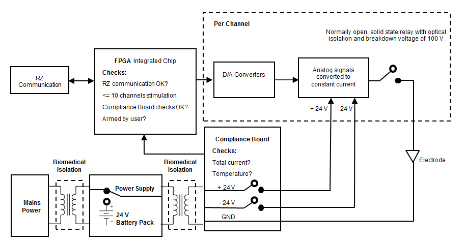 |
| IZ2M/IZ2MH Functional Safety Diagram |
The stimulator's power supply has been validated to ensure 4,000 volts of isolation between the input and output, 1,500 volts of isolation between the input and ground, and 500 volts of isolation between the output and ground. Safety approvals for the power supply include the following: UL60601-1, EN60601-1, CSA C22.2 No. 601.1 CE Mark LVD.
The Stimulator System
A typical system consists of an RZ processor equipped with a specialized DSP (RZDSP-I or QZDSPO) and additional fiber optic connector on the back panel.
The block diagram below illustrates the functionality of the system.
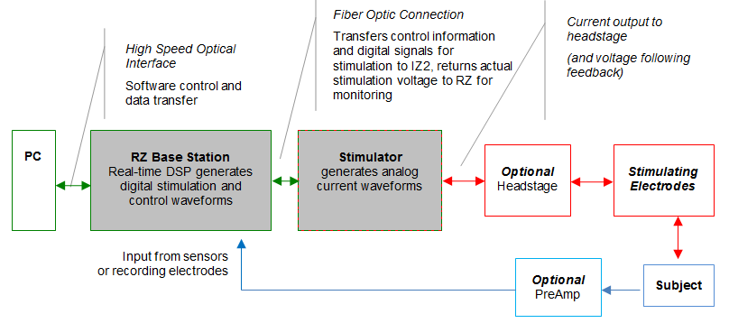 |
| Multichannel Stimulator System Diagram |
Stimulation control waveforms for each electrode channel are first defined on the RZ base station and digitally transmitted over a fiber optic cable to the stimulator. On the stimulator, specialized circuitry for each electrode channel generates an analog voltage waveform. Analog-to-digital (A/D) converters read the output voltage for a chosen bank of 8 channels and send that information back to the RZ for monitoring.
Hardware Set-up
To connect the system hardware:
Ensure that the TDT drivers, PC interface, and RZ and zBus devices are installed, setup, and configured according to the installation guide provided with your system.
Connect to RZ Base Station
Connect the stimulator to the base station using the provided duplex fiber optic cable.
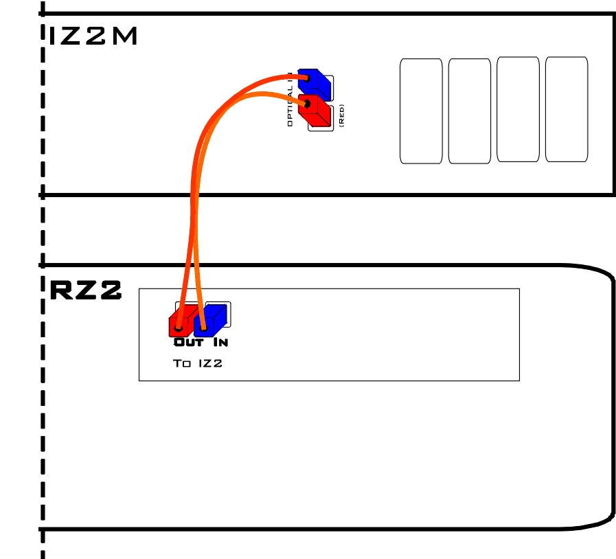
Connect the fiber optic cable from the stimulator's fiber optic port labeled Fiber to the fiber optic port labeled To IZ2 on the back side of the RZ. Use the RED labels to match up the color coded fiber connectors and be sure to line up the notch and keys on each.
Connect electrodes
Connect the DB26 output connectors on the stimulator to the stimulating electrodes using your preferred method, such as direct wiring or a custom pass through connector (available from TDT). See IZ2M/IZ2MH Stimulator Technical Specifications for pinouts.
Power on
Power on the RZ base station, then power on the stimulator by pressing and holding the small square button to the left of the status lights. After one second, release the button.
The stimulator is powered on using battery for operation.
Important
The IZ2M/IZ2MH uses mains power for charging. Connect the power connector on the back panel to a mains power outlet, using the provided AC power cable. The battery is always charging when the mains power switch is in the ON position, regardless of whether the IZ2M/IZ2MH is turned on.
When battery power is turned on, the blue LED on the mains power switch, to the right of the status button, will be lit even when the mains power is off (used to indicate temperature). Verify whether mains power is on or off by looking at the position of the switch and by looking at the left-most power status LED. It will be red when the device is using battery power or green when the device is using Mains power.
The hardware is ready for use
If using the system with other devices, or preamplifiers, see the documentation for those devices for hardware connection information.
Arming Sequence
Before the stimulator can be armed the RZ2 must be connected to the stimulator and powered on. If the stimulation circuit is loaded and running, it MUST not be actively sending stimulus signals on any channels.
The instructions below provide step-by-step sequence and more detail about each stage of device operation.
Step one. Boot - turn power on
When the device is powered on (see above) the blue LED blinks until the device comes up to optimal temperature. This can take up to 10 minutes. If no faults are found at start-up, the stimulator may be armed before optimal temperature is reached (not recommended).
If a safety fault condition is found at start-up; the blue LED will blink at 1 Hz and the yellow LED will be off.
If a communication error occurs, such as no signal detected from the RZ device, is found, or the RZ is trying to actively stimulate, the yellow Ready LED will blink.
When all safety checks have passed both the blue (mains power) and yellow (Ready) LEDs will be lit (no flashing). The device is ready to arm.
Step two. ARM - hold down the Start/Stop button for 3 seconds
When the red LED flashes the Start/Stop button may be released and the red (Armed) LED will remain lit. If any fault is detected the red LED will not come on (or turn off) and the blue LED will begin to blink at 1 Hz.
Step three. Stimulate - send stimulation (up to 10 channels) from the RZ processor
Once the device is armed, it is under the control of the RZ processor. If the RZ is not actively controlling the IZ2M, the default state is channels are closed and output set to zero current. The stimulator will deliver stimulation to the subject whenever stimulation signals are received from the RZ processor.
The stimulator faults and returns to safe mode (all channels open/no voltage output possible) if any of the below occurs:
-
Stimulation is attempted on more than 10 channels.
-
More than 100 mA total output is detected by the compliance board. Note: It is not possible to reach 100 mA under normal software controlled conditions.
-
IZ2_Control macro in RPvdsEx is set to Voltage mode instead of Current mode.
See your software documentation for end user applications.
Step four. STOP - press Start/Stop button
The user can press the Start/Stop button at any time to stop stimulation immediately and revert to safe mode.
Status LEDs
A blue LED is located on the on/off switch on the right side of the stimulator's front panel. It reports power on/off state and indicates temperature and over voltage faults. On the left side of the device, there is a Start/Stop button for arming the device with adjacent yellow (Ready) and red (Armed) LEDs that report any communication errors and armed status. Between the Battery on/off button and the Mains on/off switch there is a row of power status LEDs.
The chart below compiles the various stages of operation and blue, yellow, red LED status for each.
* The Blue LED is primarily used to indicate power on/off and safety ok/fault. However, when the IZ2M/IZ2MH is actively stimulating (no faults) it also indicates temperature deviation from optimal by blinking off (short off duration) with the frequency of the off blink indicating the number of degrees off from optimal.
Power Status LEDs
Immediately to the left of the mains power button there is a row of small LEDs. The first LED (from left) indicates whether the devices is being powered from mains or battery power.
The four LEDs on the right end of the row indicate the power level of the battery.
The LED between the Power Mode LED and the Power Level LEDs is not used at this time.
Testing the System
The IZ2M includes a resistor block that is used to verify stimulation output. The RB100 is a 100 kOhm resistor block that is included with the IZ2M. The RB10 is a 10 kOhm resistor block that is included with the IZ2MH. In Synapse, use the impedance test built into the IZ2n HAL object at run time to verify that the correct impedance is measured. Download the test files and instructions from https://www.tdt.com/files/tech/IZ2ImpedanceTest.zip.
IZ2M/IZ2MH Features
Analog Outputs (Stim Outputs)
The analog output channels are arranged in sixteen-channel banks.
Stim Lights
The Stim Lights are located on the front plate of the IZ2M/IZMH and are labeled by channel number. Each LED indicates the voltage at the corresponding electrode site. The Stim Light will turn green when a channel has greater than ±150 mV at the output and will turn red when a channel output is beyond ±10 V.
Fiber Optic Port (Fiber)
The fiber optic input port provides an isolated connection to the RZ base station. One end of the fiber optic cable connects to the stimulator fiber optic input port (labeled Fiber) and the other end connects to the fiber optic input port (labeled 'To IZ') on the front panel of a RZ5D or the back panel of other RZ base stations. See Hardware Set-up connection diagram.
Battery Operation and Charging
The stimulator has an onboard, 240 Wh battery for device operation. The battery charges whenever the Mains power is connected and the Mains power switch is in the on position.
Software Control
Synapse
Operation of the stimulator system is controlled by an IZ2 object in the Synapse Rig and Processing Tree. Consult the Synapse Manual for more detailed information on general Synapse use.
Ensure that hardware your rig is properly set up in the Rig Editor (Menu > Edit Rig) and you have the required elements: RZ processor, RZDSP-I (or QZDSPO with optics) and IZ2 stimulator.
Important
Make sure the IZ2 object has the correct model selected (IZ2M or IZ2MH) and channel count.
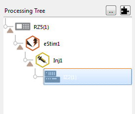
A typical electrical stimulation experiment includes an Electrical Stimulation gizmo to generate monophasic or biphasic pulses, then a Signal Injector gizmo which routes this single channel signal to one or more channels in a multi- channel stream and determines what the non-stim channels are doing (typically set to "IZ2 Open" mode), and then this multi-channel stream connects to the IZ2 object to control all channels on the IZ2 at once.
Important Experiment Design Considerations
Sampling Rate
The IZ2M/IZ2MH can control 64 channels at up to 50 kHz. The stimulator sampling rate is the same as the sampling rate of the circuit running on the RZ device, so the maximum sampling rate of the stimulator is also limited to the maximum sampling rate of the type of RZ device controlling it.
Signal Resolution
Signal resolution is dependent on the sampling rate used. PCM D/A converters allow users to generate precise pulsed signals, including square waves with durations of only 1 sample.
Designing the Stimulus Signal
The IZ2M/IZ2MH Stimulator system offers flexible stimulus delivery capable of generating complex patterns of pulses or arbitrary waveforms.
This allows you to make use of the full range of the stimulation gizmos in the Synapse library, or create your own user gizmo for custom stimulation patterns.
The Signal Injector gizmo provides default values for the non-stimulating channels. This can be zero current or open circuit for the IZ2M/IZ2MH. Use the IZ2 object settings to enable the shunt resistors on all channels and to toggle voltage or current mode.
Ensure no more than ten channels have non-zero stimulus.
Monitoring the Stimulation
Eight PCM A/D converters on the stimulator monitor the actual output voltage for a chosen bank of channels and send that information back to the RZ. This information is available from the output of the IZ2_Control macro. The MonBank macro input specifies which bank of eight channels is updating on the Monitor output (the rest of the channels of the Monitor output will be latched). A zero indicates that the first bank of eight is monitored.
Note
The onboard A/D converters provide the feedback clip at ±20 V, which is higher than any possible output.
IZ2M/IZ2MH Stimulator Technical Specifications
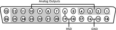
Mini-DB26 Connector Pinouts for the IZ2M/IZ2MH
Stim Output Connector
Note
See Tech Note 0896 before attempting to make any custom connections.