ACO32/ACO64 Motorized Commutators
Overview
The ACO32 and ACO64 (Active Commutator with Optogenetic stimulation) are motorized commutators that actively track rotation on a headstage cable connected to an awake, behaving subject. They spin the motor to compensate, eliminating turn-induced torque at the subject's end of the cable. The commutator is typically used for systems acquiring neural recordings from up to 32 or 64 channels when using a PZ5 analog amplifier or up to 256 channels or 512 channels when using ZD digital headstages and a PZ5 digital amplifier.
Built-in electrical shielding ensures an ultra-quiet environment for recording and lightweight cables and connectors minimize the torque caused by subject motion. Pushbuttons allow for optional manual control of the commutator motor, and an input BNC can be used to inhibit the motor during critical recording periods. A banana jack provides access to ground, so that users can connect the commutator ground to an external ground, such as a Faraday cage, to minimize ground loops.
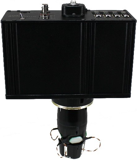
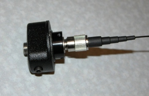
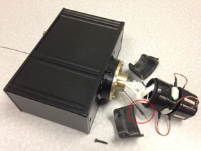
Optionally, a fiber optic rotary joint with single-channel optical fiber assembly may be added (shown above) to allow optical targeting and excitation on neural circuits for artifact free stimulation. The optical assembly is user serviceable to allow for easy optical fiber replacement.
Part numbers:
ACO32 - 32 Channel Commutator
ACO64 - 64 Channel Commutator
FORJ - Fiber Optic Rotary Joint and Fiber Optic Cable
Power and Interface
The ACO32 has a rechargeable 1950 mAh Li-ion Battery. The ACO64 has a 3900 mAh battery. A 6-9 V, 3A, center negative adapter (one provided) charges the device. Low battery status is reported only by a decrease in rotational speed.
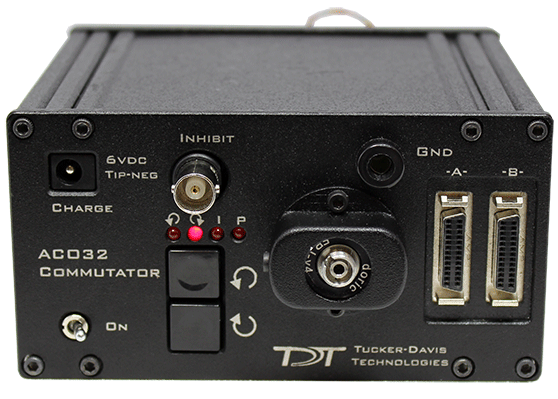
ACO32 Hardware Setup
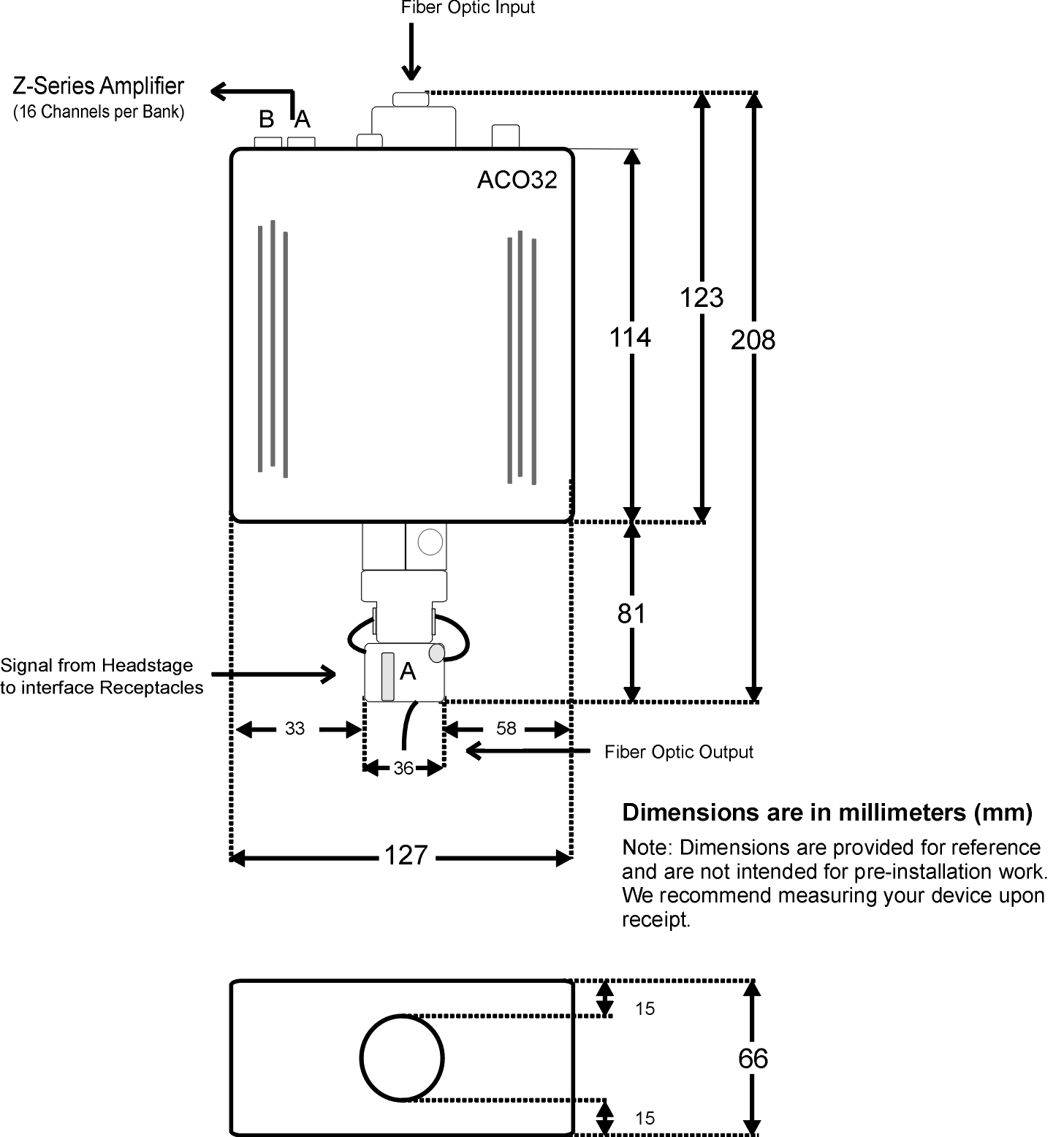
The commutator is mounted above the subject. A PZ preamplifier is connected to the DB26 connectors marked A and B on the face of the commutator. A headstage (with splice connector) and a splice-to-splice adapter are connected to the interface receptacles on the connector module. See Headstage Connections below for more information on this connection.
See ACO32 Dimensions for mounting dimensions.
Note
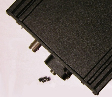
The motor in the ACO32 commutator is attached to a plate designed to allow it to be disengaged for testing and troubleshooting noise issues. The plate may slide out of normal position during shipping or anytime the commutator is turned upside down.
If the motor is not engaged, you can turn the bottom section of the rotating shaft, but the rest of the shaft does not follow.
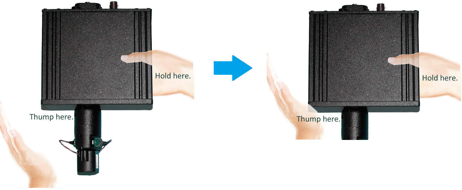
To reengage the motor:
-
Hold the commutator with the faceplate up.
-
Grip one side of the commutator.
-
Bring the commutator down to thump the bottom corner with the heel of your palm, as shown below.
ACO64 Hardware Setup
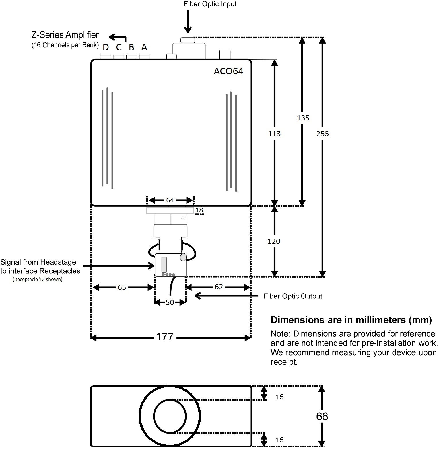
The ACO64 commutator is analogous to the ACO32 and also typically mounted above the subject. A PZ preamplifier is connected to the DB26 connectors marked A, B, C, and D on the face of the commutator. A headstage (with splice connector) and a splice-to-splice adapter are connected to the interface receptacles on the connector module. See Headstage Connections below for more information on this connection.
See ACO64 Dimensions for mounting dimensions.
Note
The motor in the ACO64 commutator does not disengage like the ACO32. The ACO64 has an additional hardware mount on the bottom, below the headstage receptacles, facing the subject.
Features
LEDs
The four indicator LEDs on the front panel indicate power, the status of the Inhibit BNC input, clockwise rotation and counterclockwise rotation.


Manual Rotational Buttons
The commutator features both clockwise and counterclockwise manual rotational buttons. When pressed, these buttons will rotate the commutator at approximately 18 RPM. Pressing either of these buttons also overrides the current rotational state of the commutator.
Inhibit BNC
During critical recording periods it may be necessary to prevent rotation to ensure signal integrity. A logical low (0) on the Inhibit BNC will prohibit any rotation initiated by either the sensors on the commutator or the manual rotational button.
External Ground
A banana jack located on the face (GND) provides connections to common ground on the commutator.
The external ground is optional and should only be used in cases where the subject must occasionally make contact with a metal surface that isn't tied to the animal ground, such as a lever press. When contact is made, a ground loop is formed that temporarily adds extra noise to the system. Grounding this metal surface directly to the TDT hardware removes this ground loop at the cost of raising the overall noise floor a small amount.
A cable kit is provided to ensure cables used with the external ground are suitable for this use. Each kit includes: one male banana plug to male banana plug pass through and one male banana plug to alligator clip pass through. These cables also include ferrite beads to remove any potential RF noise that might travel through the cable. For best results position the ferrite bead close to the source of the RF noise.
Headstage Connections
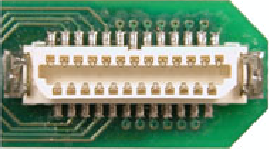
Two or four interface receptacles are positioned on the rotary interface module. The receptacles are labeled to correspond to the DB26 connectors on the face. The ACO32 uses 'A' and 'B' labels, the ACO64 uses 1 to 4 silver marks on the receptacles. TDT offers headstages and connectors with a mate for these receptacles.
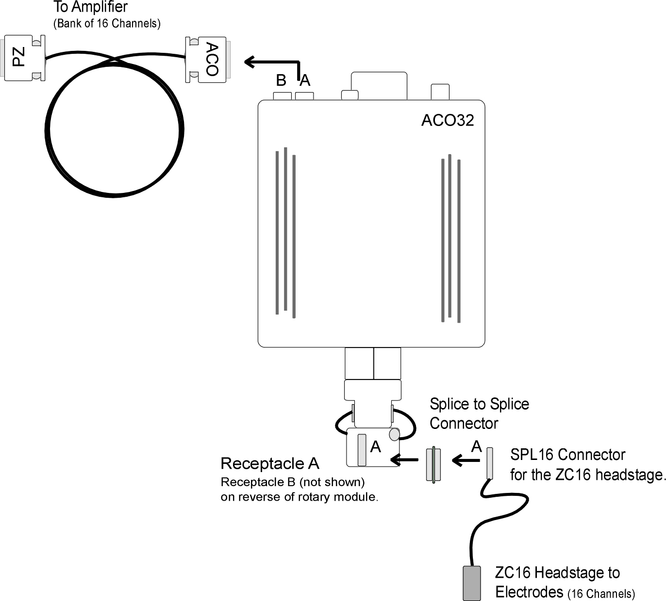
The diagram above shows the ACO32 connection for the A subset of channels:
-
from headstage (with SPL16 analog or SPL16-D digital connectors)
-
to splice-to-splice connector
-
to commutator receptacle
-
to amplifier connection cable.
Channel numbers correspond to the amplifier bank of channels to which the cable is connected. For example, if the 'A' connector is connected to Bank 'A' on the PZ5 preamplifier, channels are numbered 1 - 16.
Amplifier Connections
The ACO commutator interfaces with a PZ amplifier via two or four DB26 connectors, 16 analog channels each) on the face. Adapter cables may also be used for connections to Medusa Preamps.
See ACO Technical Specifications for connector pinout.
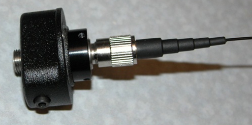
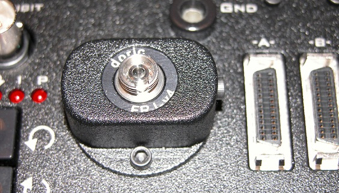
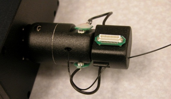
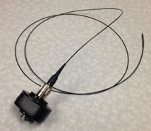
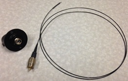
Fiber Optic Rotary Joint
The fiber optic rotary joint (FORJ) assembly is an available add-on component. It includes an FC/FC optical fiber connector accessible on the commutator face and a single channel optical fiber threaded through the module. The default fiber optic cable included with the system is 200 um core diameter, 0.22 NA, with a 1.25 mm OD metal ferrule. FORJ is also compatible with branched optical fibers of up to four bundles in the ACO64.
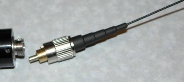
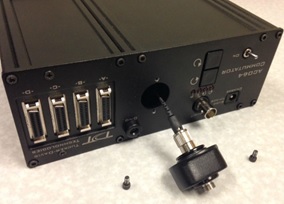
Replacing the Optical Fiber (ACO32)
The FORJ assembly can be removed and re-installed by the user to replace the optical fiber.
To remove a currently installed FORJ:
-
Use a 3/32" Allen hex driver to remove the two screws securing the fiber optic rotary joint to the commutator face.
-
Use the hex driver to remove two screws securing the encoder clamping plates.

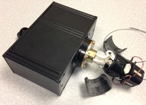
-
Carefully pull the FORJ away from the commutator face until the fiber is free.
-
Disconnect the fiber from the joint.
-
Replace the fiber.
To install the FORJ:
-
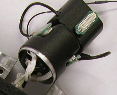
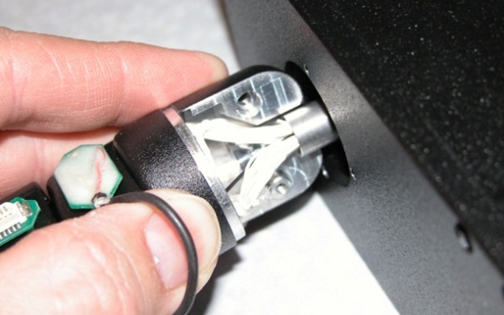
Insert metal cannula end of fiber into center of gear inside of ACO32.
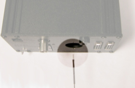
-
Slowly push fiber through hole until the end appears among the wires on the other side of the ACO32.
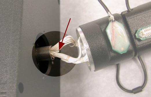
-
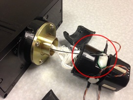
Using a pair of tweezers, carefully pull the end of the fiber and insert it into the hole next to the encoder.
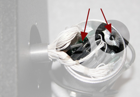
-
Pull the end of the fiber through the hole and insert it through the hole in the groove of the connector module.
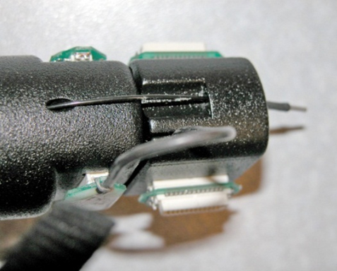
-
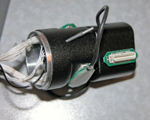
Leave enough slack in the section of fiber between the encoder and connector modules to match the loop of the other wires. A small lightweight tie can be loosely attached to hold the fiber adjacent to the wires.
-
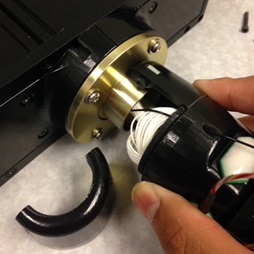
Connect the FC/PC connector end of the fiber to (the smaller section of) the fiber optic rotary joint.
-
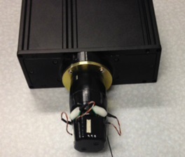
Slowly pull all of the excess fiber through the ACO32 until the FC/PC connector is inside the ACO32 and the fiber optic rotary joint plate can be attached to the ACO32 plate.
-
Attach the encoder clamping plates back onto the ACO32 shaft by tightening the two screws.
The plate should be just below body of the ACO32 and the encoder body should sit snuggly inside the lip of the clamping plates. Be careful not to pinch any wires or the fiber as the plates are tightened together.
Note
If a FORJ is not used, the through-hole can be used for other related applications (e.g. fluid delivery system). Contact TDT for more details or assistance.
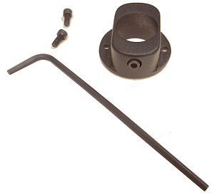
Change Kits
TDT provides two kits for users removing or adding a FORJ after initial purchase.
If you purchased the ACO32 or ACO64 without a FORJ and then add one, use the kit below to mount the new optics to the ACO32 or ACO64 faceplate.
If you purchased the ACO32 or ACO64 with a FORJ and wish to remove it, use the kit below to cover the opening where the FORJ was previously mounted.
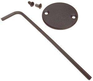
Note
The two configurations use different screws, so be sure to save all screws.
Replacing the Optical Fiber (ACO64)
The FORJ assembly can be removed and re-installed by the user to replace the optical fiber.
To remove a currently installed FORJ:
-
Use a 3/32" Allen Hex driver to remove the two screws securing the fiber optic rotary joint to the commutator face.
-
Use the hex driver to remove the two screws securing the encoder clamping plates.
-
Carefully pull the FORJ away from the commutator face until the fiber is free.
-
Disconnect the fiber from the joint.
-
Replace the fiber.
To install one optical fiber in the FORJ:
-
Insert metal cannula end of the fiber into center of gear inside the ACO64.
-
Slowly push fiber through hole until the end appears among the wires on the other side of the ACO64. Carefully pull the wire through the slip ring.
-
Insert and guide the fiber through a hole in the encoder cover, then pull through.
-
Secure the two encoder clamping shells back onto the ACO64 shaft by inserting and tightening the two screws.
-
The plate should be just below the body of the ACO64 and the encoder body should sit snugly inside the lip of the clamping plates. Be careful not to pinch any wires or the fiber as the plates are tightened together.
ACO Technical Specifications
ACO32 Dimensions
ACO64 Dimensions
Interface Receptacles
The interface receptacle diagram shows how the pins on each receptacle map to the pins on the associated DB26 connector on the face of the commutator. See pinouts below for the appropriate model.
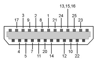 |
| Diagram reflects pin numbers (not channel numbers). |
For information on making custom connections to the commutator, see Tech Note TN0896.
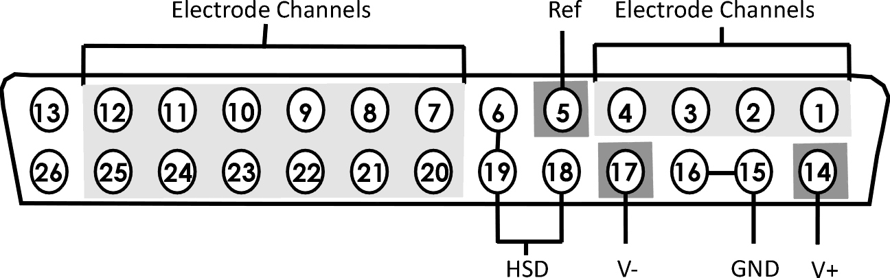
ACO32 and ACO64 Amplifier Connector Pinout
Connectors are labeled A and B on ACO32 and A, B, C, D on ACO64. Electrode channels below are relative to the electrode/headstage connected to the corresponding interface receptacle.
Note
When mapping channel numbers for recording purposes, the preamplifier connections must be taken into account. The first channel as labeled above is relative to the amplifier bank of channel numbers connected. If connector 'B' on the ACO32 is connected to Bank B on the preamplifier, E1 is channel 17.
Important
When using digital headstages and a PZ5 or PZD, channel mapping is handled by the PZ5 or PZD and channels will be ordered consecutively beginning with Connector 'A' on the commutator.